
Poorly Drawn Parallelograms: Angle-Controlled Geometry
Loading the math board and drawing, please wait…
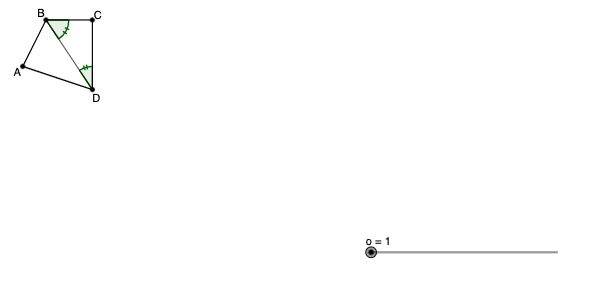
This example demonstrates how “imprecisely drawn” parallelograms can deviate from the expected geometric relationships when the defining constraints (especially angle/direction conditions) are not enforced. It centers on core geometry ideas: the properties of parallelograms, constructing polygons from vertices, and using angle constraints to control the orientation of sides. Construction-wise, GeoGebra commands Polygon, Segment, and Angle are used to build quadrilaterals with points A, B, C, D and their segments, then introduce multiple variants (A1–D1, A2–D2, A3–D3, A4–D4) controlled through corresponding angle objects (q1, q1_1, q1_2, q1_3) and related parameters (a, b, c, d). The learning goal fits middle/high school geometry lessons and classroom explorations on how angle-driven construction affects whether a quadrilateral truly behaves like a parallelogram.
GeoGebra Commands & Parameters
Polygon(A, B, C, D) → q1, a, b, c, dPolygon(A_{1}, B_{1}, C_{1}, D_{1}) → q1_{1}, a_{1}, b_{1}, c_{1}, d_{1}Polygon(A_{2}, B_{2}, C_{2}, D_{2}) → q1_{2}, a_{2}, b_{2}, c_{2}, d_{2}Polygon(A_{3}, B_{3}, C_{3}, D_{3}) → q1_{3}, a_{3}, b_{3}, c_{3}, d_{3}Polygon(A_{4}, B_{4}, C_{4}, D_{4}) → q1_{4}, a_{4}, b_{4}, c_{4}, d_{4}Polygon(A_{5}, B_{5}, C_{5}, D_{5}) → q1_{5}, a_{5}, b_{5}, c_{5}, d_{5}Polygon(A_{6}, B_{6}, C_{6}, D_{6}) → q1_{6}, a_{6}, b_{6}, c_{6}, d_{6}Polygon(A_{7}, B_{7}, C_{7}, D_{7}) → q1_{7}, a_{7}, b_{7}, c_{7}, d_{7}Segment(B, D) → fSegment(B_{1}, D_{1}) → gSegment(B_{2}, D_{2}) → hSegment(B_{3}, D_{3}) → iSegment(B_{4}, D_{4}) → jSegment(B_{5}, D_{5}) → kSegment(B_{6}, D_{6}) → lSegment(B_{7}, D_{7}) → mAngle(C, D, B) → αAngle(D, B, C) → βAngle(C_{1}, D_{1}, B_{1}) → γAngle(A_{1}, B_{1}, D_{1}) → δAngle(C_{2}, D_{2}, B_{2}) → εAngle(D_{2}, B_{2}, C_{2}) → ζAngle(A_{2}, B_{2}, D_{2}) → ηAngle(B_{2}, D_{2}, A_{2}) → θAngle(C_{3}, D_{3}, B_{3}) → ιAngle(B_{3}, D_{3}, A_{3}) → κAngle(A_{3}, B_{3}, D_{3}) → λAngle(D_{3}, B_{3}, C_{3}) → μAngle(C_{4}, D_{4}, B_{4}) → νAngle(B_{4}, D_{4}, A_{4}) → ξAngle(A_{4}, B_{4}, D_{4}) → οAngle(D_{4}, B_{4}, C_{4}) → ρAngle(C_{5}, D_{5}, B_{5}) → σAngle(B_{5}, D_{5}, A_{5}) → τAngle(D_{5}, A_{5}, B_{5}) → υAngle(B_{5}, C_{5}, D_{5}) → ϕAngle(C_{6}, D_{6}, B_{6}) → χAngle(B_{6}, D_{6}, A_{6}) → ψAngle(D_{6}, A_{6}, B_{6}) → ωAngle(B_{6}, C_{6}, D_{6}) → α_1Angle(C_{7}, D_{7}, B_{7}) → β_1Angle(A_{7}, B_{7}, D_{7}) → γ_1Angle(D_{7}, A_{7}, B_{7}) → δ_1Angle(B_{7}, C_{7}, D_{7}) → ε_1Polygon(E, F, G, H) → q2, e, f_1, g_1, h_1Segment(E, G) → nAngle(F, G, E) → ζ_1Angle(H, E, G) → η_1Angle(G, H, E) → θ_1Angle(E, F, G) → ι_1Polygon(I, J, K, L) → q3, i_1, j_1, k_1, l_1Segment(J, L) → pPolygon(I_{1}, J_{1}, K_{1}, L_{1}) → q3_{1}, i_{2}, j_{2}, k_{2}, l_{2}Segment(J_{1}, L_{1}) → p_{1}Angle(K, L, J) → κ_1Angle(L, I, J) → λ_1Angle(L_{1}, I_{1}, J_{1}) → μ_1Angle(J_{1}, K_{1}, L_{1}) → ν_1
AI Drawing Prompt Reference
This prompt describes drawing a set of quadrilaterals controlled by angle constraints to illustrate deviations from parallelogram properties. First, construct a basic quadrilateral ABCD using vertex positions and side lengths. Then, introduce multiple variants such as A1 to D1, each adjusted by angle parameters to change side directions. During construction, draw diagonal segments and calculate interior and exterior angles to verify if angle constraints satisfy parallelogram definitions. These quadrilaterals are not strict parallelograms because angle conditions are not fully enforced. Comparing angle relationships across variants helps visualize how angle-driven construction affects geometric properties. Maintain graph coherence to ensure clear relationships.
The prompt above was compiled from the original drawing commands and is for reference only.