
Solids Constructed from Sections
Loading the math board and drawing, please wait…
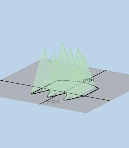
This example demonstrates the process of constructing solid figures from specific cross-sections. It involves core mathematical concepts such as solid geometry, coordinate geometry, function graphing, and matrix operations. GeoGebra commands and objects like Plane, Segment, Polygon, Sphere, Sequence, and Textfield are used in the construction. Suitable for high school students and math enthusiasts to understand spatial geometry and function applications.
GeoGebra Commands & Parameters
Plane((0, 0, 0), (0, 1, 0), (0, 1, 1)) → sPlane((a, 0, 0), (a, 1, 1), (a, 1, 2)) → cPlane((b, 0, 0), (b, 1, 1), (b, 1, 2)) → dSegment((a, f(a)), (a, g(a))) → hSegment((b, f(b)), (b, g(b))) → iIntersect(f, h) → AIntersect(g, h, (-8, -6.968074739870145)) → BIntersect(f, i) → CIntersect(g, i, (8, -1.0319252601298547)) → DPolygon(A, B, (x(B), y(B), h), (x(A), y(A), h)) → q1, a_1, b_1, t, f_1Polygon(A, B, (a, (0.5 * (y(A) + y(B))), (sqrt(3) * h / 2))) → t1, g_1, a_2, b_2Midpoint(A, B) → ESphere(E, A) → uSequence(Polygon[(a + (i * deltax), g(a + (i * deltax)), 0), (a + (i * deltax), f(a + (i * deltax)), 0), 4, s], i, 0, n - 1, 1) → L3Polygon(A, B, (x(B), y(B), h)) → t2, k, a_3, b_3Sequence(Polygon[(a + (i * deltax), g(a + (i * deltax)), 0), (a + (i * deltax), f(a + (i * deltax)), 0), 3, s], i, 0, n - 1, 1) → L4Sequence(Polygon[(a + (i * deltax), f(a + (i * deltax)), 0), (a + (i * deltax), g(a + (i * deltax)), 0), (a + (i * deltax), g(a + (i * deltax)), Distance[(a + (i * deltax), f(a + (i * deltax)), 0), (a + (i * deltax), g(a + (i * deltax)), 0)])], i, 0, n - 1, 1) → L7Line((0, 0, 0), (1, 0, 0)) → mLine((0, 0, 0), (0, 1, 0)) → rTextfield(f) → InputBox1Textfield(g) → InputBox2Textfield(a) → InputBox3Textfield(b) → InputBox4Textfield(n) → InputBox5Sequence(Prism[Element[L3, i], deltax], i, 1, n, 1) → L2Sequence(Prism[Element[L4, i], deltax], i, 1, n, 1) → L5Sequence(Polygon[(a + (i * deltax), g(a + (i * deltax)), 0), (a + (i * deltax), f(a + (i * deltax)), 0), 5, s], i, 0, n - 1, 1) → L6Sequence(Prism[Element[L6, i], deltax], i, 1, n, 1) → L8Sequence(Midpoint[(a + (i * deltax), f(a + (i * deltax)), 0), (a + (i * deltax), g(a + (i * deltax)), 0)], i, 0, n - 1, 1) → L9Sequence((a + (i * deltax), f(a + (i * deltax)), 0), i, 0, n - 1, 1) → L10Sequence(Segment[Element[L9, i], Element[L10, i]], i, 1, n, 1) → radiiSequence((a + (i * deltax), g(a + (i * deltax)), 0), i, 0, n - 1, 1) → L11Sequence(Midpoint[Element[L10, i], Element[L11, i]], i, 1, n, 1) → L12Sequence(CircleArc[Element[L12, i], Element[L10, i], Element[L11, i], s], i, 1, n, 1) → L13Sequence(Prism[Element[L7, i], (-deltax)], i, 1, n, 1) → L
AI Drawing Prompt Reference
Draw a solid figure constructed from specific cross-sections, demonstrating core mathematical concepts. Create three planes, define the graphs of two functions, and find their intersections with the planes. Use these intersections to build multiple polygons and a sphere, then generate a series of prisms through sequence operations, combining them into a complex solid structure that illustrates spatial geometry and function applications.
The prompt above was compiled from the original drawing commands and is for reference only.