
Sivas Şifaiye Geometry: Coordinate Construction with Equilateral Triangles and R
Loading the math board and drawing, please wait…
In collections
Fatin Uluengin - muqarnas
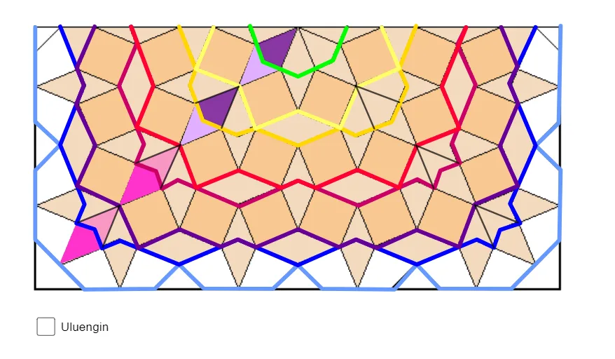
This example demonstrates how to build an ornamental, module-like geometric figure in the coordinate plane by combining line segments and polygons whose structure is governed by equilateral-triangle relationships. Key mathematical ideas include equilateral triangles (equal-length/angle constraints), geometric construction using points and segments, and assembling larger designs from repeated coordinate-defined parts. Construction-wise, it uses GeoGebra commands Segment, Point, PolyLine, and Polygon: Segment and Point generate the defining edges and vertices, PolyLine builds the polyline skeleton, and Polygon creates closed multi-sided regions. The listed objects (e.g., A, B and multiple indexed components such as S_4, T_4, U_4, V_4, W_4, Z_4, A_5–L_5) reflect layered or repeated sub-constructs that together form the final pattern. Suitable for secondary-school geometry construction, coordinate geometry practice, and classroom demonstrations of modular geometric design.
GeoGebra Commands & Parameters
Segment(S_4, T_4) → nSegment(U_4, T_4) → pSegment(V_4, W_4) → qSegment(Z_4, W_4) → rSegment(A_5, B_5) → sSegment(C_5, B_5) → tSegment(D_5, E_5) → aSegment(F_5, E_5) → bSegment(G_5, H_5) → cSegment(I_5, H_5) → dSegment(J_5, K_5) → eSegment(L_5, K_5) → f_1Point(yAxis) → MPolyLine(C, D, M, N, O, P, Q, R, S, T, U, V, E, W, F, G, H, I, J, K, L) → fPolyLine(Z, A_1, M, H_1, P, I_1, J_1, K_1, L_1, M_1, U, N_1, E, O_1, B_1, C_1, D_1, E_1, F_1, J, G_1) → gPoint(f) → M_5Polygon(M_5, E_1, D_1, C_1) → vierhoek1, m_5, e_1, d_1, c_1Polygon(E_1, T_4, C_1, D_1) → vierhoek2, g_1, t_4, h_1, i_1Point(g) → Q_1Point(g) → R_1Point(g) → T_1Point(g) → V_1Point(g) → Z_1Point(g) → A_2Point(yAxis) → B_2Point(g) → C_2Point(g) → D_2Point(g) → F_2Point(g) → H_2Point(g) → J_2PolyLine(P_1, Q_1, G_1, A_2, B_2, C_2, H_1, D_2, E_2, F_2, G_2, H_2, A_1, I_2, J_2, N_1, K_2, L_2, R_1, S_1, T_1, U_1, V_1, W_1, Z_1) → hPoint(yAxis) → V_2PolyLine(M_2, N_2, W_2, Z_2, A_3, B_3, C_3, D_3, E_3, F_3, G_3, O_2, P_2, Q_2, R_2, S_2, T_2, U_2, V_2) → iPolygon(U_1, S_2, R_2, Q_2) → vierhoek3, u_1, s_2, r_2, q_2Polygon(S_2, B_5, Q_2, R_2) → vierhoek4, j_1, b_5, k_1, l_1Point(i) → I_3Point(i) → K_3Point(i) → M_3Point(i) → N_3Point(i) → P_3PolyLine(M_2, H_3, P_3, Q_3, R_3, S_3, G_3, I_3, J_3, K_3, L_3, M_3, V_2, N_3, O_3) → jPoint(yAxis) → A_4PolyLine(T_3, U_3, E_4, F_4, G_4, V_3, W_3, Z_3, H_4, A_4, B_4, C_4, D_4) → kPolygon(G_5, J_3, I_5, W_3) → vierhoek5, g_5, j_3, i_5, w_3Polygon(I_5, H_5, G_5, W_3) → vierhoek6, m_1, h_5, n_1, p_1Point(yAxis) → K_4PolyLine(I_4, U_3, J_4, H_4, K_4, B_4, L_4, F_4, M_4) → lPoint(yAxis) → P_4PolyLine(N_4, O_4, P_4, Q_4, R_4) → mPolygon(N_5, J_4, O_5, O_4) → vierhoek7, n_5, j_4, o_5, o_4Polygon(P_5, N_5, O_4, O_5) → vierhoek8, p_5, q_1, r_1, s_1
AI Drawing Prompt Reference
Draw a decorative modular geometric figure on a coordinate plane, built from equilateral-triangle relationships. Start with several pairs of line segments that form triangle edges. Place a point on the vertical axis as a central reference. Then create two polyline skeletons that outline a symmetric shape, and place multiple points along these polylines to serve as vertices for later polygons. Using these points and existing segment endpoints, construct several quadrilaterals that are adjacent to each other, forming repeating modular units. Finally, add more polylines connecting points on the vertical axis to previously generated vertices to complete the layered, symmetric pattern. The overall design combines line segments, polylines, and polygons, emphasizing geometric construction and coordinate positioning.
The prompt above was compiled from the original drawing commands and is for reference only.