
Sierpinski Carpet Pyramid: An Iterative 3D Fractal Construction
Loading the math board and drawing, please wait…
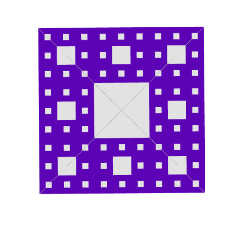
This example demonstrates how to construct a Sierpinski-carpet–style 3D fractal pyramid (a layered pyramid-like solid) using iterative geometric rules. It highlights key ideas from fractal geometry and recursive/iterative construction, together with 3D solid-geometry modeling of faces and edges. Construction workflow in GeoGebra: start with Polygon and Pyramid to define the base geometry; create crucial vertices using Point; compute edge midpoints via Midpoint to generate the next-level substructures; use Plane, OrthogonalPlane, and OrthogonalLine to set up planes and right-angled relationships in space; apply Rotate and Translate to position and orient repeated parts; and use Vector and Intersect to manage directional information and compute necessary intersection points. The model then assembles individual side faces (e.g., faceABF, faceBCF, …) and corresponding edges (e.g., arestaAF, arestaBF, …) to form the final stepped fractal pyramid shape. Suitable for advanced secondary students and undergraduate learners to visualize iteration-driven fractals and practical 3D geometric construction.
GeoGebra Commands & Parameters
Polygon(A, B, 4, xOyPlane) → pol1, f, g, h, i, C, DPyramid(pol1, 4) → b, F, faceABF, faceBCF, faceCDF, faceADF, arestaAF, arestaBF, arestaCF, arestaDFPoint(Segment[A, B], 1 / 3) → EOrthogonalLine(E, f, faceABF) → lPoint(Segment[A, E], 1 / 3) → JPoint(Segment[A, E], 2 / 3) → KOrthogonalLine(J, f, faceABF) → jOrthogonalLine(K, f, faceABF) → kIntersect(k, arestaAF) → NIntersect(arestaAF, j) → OMidpoint(O, N) → B_0Plane(B_0, xOyPlane) → pOrthogonalLine(O, p) → nOrthogonalLine(N, p) → qOrthogonalLine(N, p) → rIntersect(n, p) → B_4Rotate(B_4, 90°, B_0, p) → B_3Polygon(B_4, B_3, 4, p) → pol2, s, t, a, c, B_2, B_1Rotate(pol2, 90°, zAxis) → pol2'Rotate(pol2', 90°, zAxis) → pol2''Rotate(pol2'', 90°, zAxis) → pol2'''Midpoint(A, O) → C_0OrthogonalPlane(C_0, zAxis) → q_1OrthogonalLine(C_0, n, space) → mOrthogonalLine(C_0, m, q_1) → dPolygon(C_4, C_3, C_2, C_1) → q1, g_1, m_1, i_1, l_1OrthogonalLine(B_0, q_1) → eVector(C_0, C_0 + (Distance[B_1, B_2], 0)) → chPoint(Segment[F, A], 1 / 3) → A_4Point(Segment[F, B], 1 / 3) → A_3Plane(A_4, q_1) → r_1Polygon(A_4, A_3, 4, r_1) → poly1, f_1, h_1, j_1, k_1, A_2, A_1Vector(B_0, B_0 + (Distance[A_1, A_2], 0)) → bhVector(B_0, B_0 + (0, Distance[A_1, A_2])) → bvVector(C_0, C_0 + (0, Distance[B_1, B_2])) → cvTranslate(pol2, bv) → pol2'_{1}Translate(pol2''', bh) → q2Translate(pol2', bv) → pol2''_{1}Translate(q_1, Vector[(0, 0, 0)]) → p_1Translate(pol2, bh) → pol2'_{2}Translate(p_1, Vector[(0, 0, 0)]) → p_2Translate(q1, cv) → q1'Translate(q1', cv) → q1''Translate(pol1, u) → pol1'Translate(q1'', ch) → q1'''Translate(q1, ch) → q1'_{1}Translate(q1'_{1}, ch) → q3Translate(q3, cv) → q3'Translate(q3', cv) → q3''Translate(q1'', bv) → q1'''_{1}Translate(q1''', bv) → q4Translate(q3'', bv) → q3'''Translate(q1', bv) → q1''_{1}Translate(q1, bv) → q1'_{2}Translate(q1'_{1}, bv) → q5Translate(q3, bv) → q3'_{1}Translate(q3', bv) → q3''_{1}Translate(q3, bh) → q3'_{2}Translate(q3', bh) → q3''_{2}Translate(q3'', bh) → q3'''_{1}Translate(q1''', bh) → q6Translate(q1'', bh) → q1'''_{2}Translate(q1', bh) → q1''_{2}Translate(q1, bh) → q1'_{3}Translate(q1'_{1}, bh) → q7Translate(xOyPlane, Vector[(0, 0, 0)]) → xOyPlane'Translate(q1'''_{1}, bv) → q8Translate(q1''_{1}, bv) → q9Translate(q1'_{2}, bv) → q10Translate(q5, bv) → q5'Translate(q3'_{1}, bv) → q11Translate(q3''_{1}, bv) → q12Translate(q3''', bv) → q13Translate(q4, bv) → q4'Translate(q13, bh) → q13'Translate(q4', bh) → q4''Translate(q8, bh) → q8'Translate(q9, bh) → q9'Translate(q10, bh) → q10'Translate(q5', bh) → q5''Translate(q11, bh) → q11'Translate(q12, bh) → q12'Translate(q1'''_{2}, bh) → q14Translate(q6, bh) → q6'Translate(q3'''_{1}, bh) → q15Translate(q1''_{2}, bh) → q16Translate(q1'_{3}, bh) → q17Translate(q7, bh) → q7'Translate(q3'_{2}, bh) → q18Translate(q3''_{2}, bh) → q19Translate(q14, bv) → q14'Translate(q16, v) → q16'Translate(q16', bv) → q16''Translate(q17, bv) → q17'Translate(q7', bv) → q7''Translate(q19, bv) → q19'Translate(q15, bv) → q15'Translate(q6', bv) → q6''Translate(q18, bv) → q18'Translate(q13', bh) → q13''Translate(q4'', bh) → q4'''Translate(q8', bh) → q8''Translate(q9', bh) → q9''Translate(q10', bh) → q10''Translate(q5'', bh) → q5'''Translate(q11', bh) → q11''Translate(q12', bh) → q12''
AI Drawing Prompt Reference
Draw a 3D fractal pyramid inspired by the Sierpinski carpet. Start with a square base and a four-sided pyramid. Mark points at one-third along a base edge and draw perpendicular lines to intersect the pyramid's side edges. Construct a square plane parallel to the base between the base and apex, then rotate it three times around the vertical axis to create a stepped layer. Add smaller squares on the side faces and translate copies across the pyramid to form a repeating, nested pattern of shrinking squares, resulting in a layered fractal solid with visible faces and edges.
The prompt above was compiled from the original drawing commands and is for reference only.