
Sextant: Geometric Construction and Angle Measurement Simulation
Loading the math board and drawing, please wait…
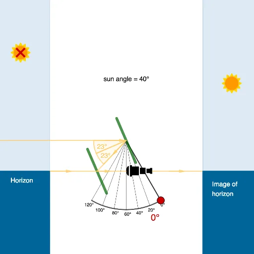
This GeoGebra example dynamically simulates the working principle of a sextant, demonstrating how reflection and angle addition are used to measure the altitude of celestial bodies. Core mathematical concepts include the law of reflection, angle equality, triangle angle sum, and relationships between central angles and arcs. Construction highlights: Sequence generates a series of arcs, CircleArc draws the graduated scale, Point and Angle mark key vertices and angles, Segment and Line build the mirror frames, Vector and Translate handle translations, Rotate rotates the index arm, OrthogonalLine constructs perpendiculars, Mirror performs light reflection, Ray simulates incident light, Sun object represents the celestial body, and Polygon with Midpoint assists in structural framing. This example is suitable for high school physics or mathematics lessons on geometric optics and angle measurement, as well as interdisciplinary teaching in navigation or astronomy, helping students intuitively understand how a sextant converts celestial altitude into a readable scale via double mirror reflection.
GeoGebra Commands & Parameters
Sequence(((r_1 * cos(270° + i°)), (r_1 * sin(270° + i°))), i, -30, 30, 10) → points1Sequence(Segment[(0, 0), Element[points1, i]], i, 1, Length[points1]) → seg1CircleArc((0, 0), ((r_1 * cos(240°)), (r_1 * sin(240°))), ((r_1 * cos(300°)), (r_1 * sin(300°)))) → dPoint(d) → AAngle(A, (0, 0), ((r_1 * cos(300°)), (r_1 * sin(300°)))) → αSequence(Text[140 - (i * 20) + "°", Element[points1, i] - (If[i < 7, If[i < 3, 0.35, 0.1], 0], 0.3)], i, 1, Length[points1]) → L_1Segment((0, 0), A) → fCircle(B, 1.2) → eIntersect(f, xAxis) → OPoint(e) → ELine(E, B) → gIntersect(e, g, 2) → FSegment(E, F) → hVector(B, O) → uTranslate(E, u) → E'Translate(F, u) → F'Segment(E', F') → h'Rotate(E', (-α), O) → E''Rotate(F', (-α), O) → F''Segment(E'', F'') → h''OrthogonalLine(B, yAxis) → iPoint(i) → GMirror(G, yAxis) → G'OrthogonalLine(G, i) → jIntersect(j, xAxis) → HRay(H, H + (0, 1)) → kPoint(k) → ISun(I, r) → p, L_3Point(xAxis) → JRotate(J, (-2 * α), O) → J'Ray(O, J') → lVector(J', O) → wIntersect(j, l) → KVector(I, K) → vSun(L, r) → q, L_4Point(i) → MMirror(M, yAxis) → M'Polygon(M - (10, 0), M, 4) → poly1, m, n, s, t, N, PPolygon(M', M' + (10, 0), 4) → poly2, a, b, c, f_1, Q, RPolygon(M, M - (10, 0), 4) → poly3, g_1, h_1, i_1, j_1, S, TPolygon(M' + (10, 0), M', 4) → poly4, k_1, l_1, m_1, n_1, U, VIntersect(e, i, 2) → WVector(M, W) → u_1Midpoint(O, B) → ZVector(O, Z) → v_1Segment(O, B) → p_1Intersect(i, yAxis) → A_1Midpoint(B, A_1) → B_1Vector(B, B_1) → w_1Point(i) → C_1Midpoint(C_1, M') → D_1Vector(C_1, D_1) → a_1OrthogonalLine(O, h'') → q_1OrthogonalLine(M, xAxis) → s_1Intersect(q_1, s_1) → E_1Intersect(s_1, l) → F_1Angle(F_1, O, E_1) → δLine(O, B) → t_1Intersect(s_1, t_1) → G_1Angle(E_1, O, G_1) → γAngle(H, O, I) → βPoint(i) → H_1Segment(H_1, M') → c_1Segment(M, A_1) → b_1
AI Drawing Prompt Reference
Draw a geometric construction of a sextant. Start with a circular arc centered at the origin, spanning from 240 to 300 degrees, with radial lines every 10 degrees and angle labels. Place a point on the arc and connect it to the center. On the right, construct a small circle with a diameter line, then add perpendicular lines and mirror them across the vertical axis. Translate and rotate these elements to form the index arm. Add a vertical reference line with points and their reflections to create the mirror frame. Draw a ray from above that reflects off the mirror and points toward the arc, and include a sun symbol. Finally, add polygonal base and support structures, marking key intersections and midpoints.
The prompt above was compiled from the original drawing commands and is for reference only.