
Right Circular Cylinder!
Loading the math board and drawing, please wait…
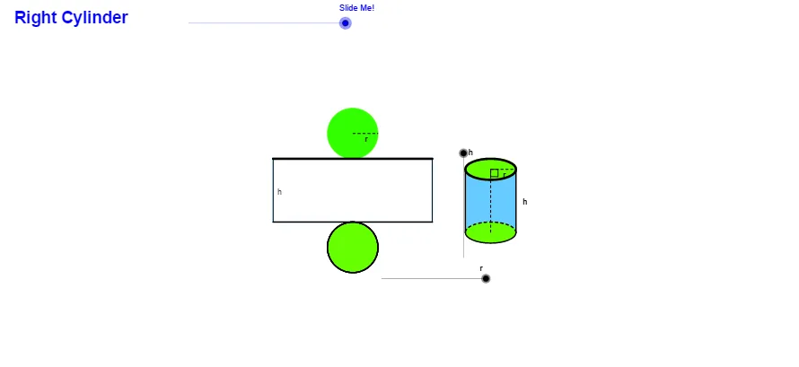
This example demonstrates the construction of a right circular cylinder. Key mathematical concepts include circles, solid geometry, and geometric construction. Using GeoGebra commands such as Point, Circle, Intersect, etc., the various components of the cylinder can be constructed. Suitable for middle school and above students or teachers.
GeoGebra Commands & Parameters
Point(xAxis) → ACircle(A, r) → cIntersect(c, xAxis) → B, CEllipse(E, D, C) → eIntersect(xAxis, yAxis) → FVector(F, G) → uTranslate(B, Vector[(u * h)]) → B'_1Translate(C, Vector[(u * h)]) → C'_1Translate(A, Vector[(u * h)]) → A'Translate(e, Vector[(u * h)]) → e'_1Polygon(B'_1, B, C, C'_1) → poly1, b', b, c_1, c'Arc(e'_1, C'_1, B'_1) → fArc(e, B, C) → gArc(e, C, B) → kArc(e'_1, C'_1, B'_1) → p_5Arc(e'_1, B'_1, C'_1) → qArc(e, B, C) → sSegment(A', A) → h_6Segment(A', C'_1) → pAngle(A, A', C'_1) → αLine(A, A') → jIntersect(e'_1, j) → H, IIntersect(k, j) → J,Circle(I, r) → tIntersect(t, j, 2) → KCircle(K, I) → d_1Circle(J, r) → e_1Intersect(e_1, j, 1) → LCircle(L, J) → f_1Intersect(f_1, j, 2) → MIntersect(d_1, j, 2) → NIntersect(s, j) → O,Vector(H, N) → vVector(O, M) → wTranslate(H, Vector[(v * n)]) → H'_1Translate(D, Vector[(u * h)]) → D'Translate(E, Vector[(u * h)]) → E'Line(B, B'_1) → lLine(C, C'_1) → mIntersect(d_1, l, 1) → PIntersect(d_1, m, 1) → QVector(B'_1, P) → zVector(C'_1, Q) → u_1Translate(B'_1, Vector[(z * n)]) → B''Translate(C'_1, Vector[(u_1 * n)]) → C''Midpoint(B'_1, A') → RMidpoint(B, A) → SLine(R, S) → a_1Intersect(q, a_1) → T,Intersect(d_1, a_1, 1) → UVector(T, U) → v_1Translate(T, Vector[(v_1 * n)]) → T'Intersect(f_1, l, 1) → VIntersect(f_1, m, 1) → WIntersect(f_1, a_1, 2) → ZIntersect(s, a_1) → A_1,Vector(B, V) → w_1Vector(A_1, Z) → z_1Vector(C, W) → b_1Translate(B, Vector[(w_1 * (n - 1))]) → B'Translate(A_1, Vector[(z_1 * (n - 1))]) → C_1Translate(O, Vector[(w * (n - 1))]) → O'Translate(C, Vector[(b_1 * (n - 1))]) → C'If(n ≟ 0.02, B'_1, If[n < 1, B'', P]) → B_1If(n ≟ 0.02, T, If[n < 1, T', U]) → D_1If(n ≟ 0.02, H, If[n < 1, H'_1, N]) → E_1If(n ≟ 0.02, C'_1, If[n < 1, C'', Q]) → F_1Conic(B_1, D_1, E_1, F_1, I) → g_1Conic(I, B_1, D_1, E_1, F_1) → h_1If(n < 1, B, If[n < 2, B', V]) → G_1If(n < 1, A_1, If[n < 2, C_1, Z]) → H_1If(n < 1, O, If[n < 2, O', M]) → I_1If(n < 1, C, If[n < 2, C', W]) → J_1Conic(G_1, H_1, I_1, J_1, J) → k_1Vector(H, O) → i_1Translate(H, Vector[(i_1 * (n - 2))]) → H'If(n < 2, H, If[n < 3, H', O]) → K_1Segment(H, K_1) → j_1Arc(e, B, C) → q_1Intersect(g, k_1) → M_1, N_1, R_1, S_1Arc(k_1, M_1, N_1) → r_1Arc(k_1, N_1, M_1) → p_1Arc(e, C, B) → s_1OrthogonalLine(I, j) → l_1OrthogonalLine(J, l) → m_1Circle(I, w_2) → t_1Intersect(t_1, l_1, 1) → L_1Intersect(t_1, l_1, 2) → O_1OrthogonalLine(O_1, l_1) → n_1OrthogonalLine(L_1, m_1) → a_2Intersect(m_1, n_1) → P_1Intersect(m_1, a_2) → Q_1Circle(H, r) → c_2Intersect(c_2, j, 2) → T_1Circle(T_1, H) → d_2OrthogonalLine(H, j) → b_2Intersect(d_2, l_1, 1) → U_1OrthogonalLine(T_1, j) → e_2Intersect(d_2, e_2, 1) → V_1Angle(U_1, T_1, V_1) → βCircle(L_1, r) → f_2Intersect(f_2, l_1, 2) → W_1Vector(I, W_1) → u_2Translate(d_2, Vector[(u_2 * (n - 3))]) → g_2Center(g_2) → Z_1Intersect(g_2, b_2) → A_2, B_3Rotate(A_2, w_3, Z_1) → B_2If(n < 3, H, If[n < 4, B_2, L_1]) → C_2Mirror(C_2, j) → D_2Mirror(E_2, j) → F_2Midpoint(I, L_1) → G_2Intersect(m, l_1) → H_2Midpoint(H_2, C'_1) → I_2Vector(H_2, G_2) → v_2OrthogonalLine(C'_1, m) → i_2Polygon(D_2, F_2, E_2, C_2) → poly2, d_3, f_3, e_3, c_3Vector(C'_1, W_1) → z_2Translate(C'_1, Vector[(z_2 * (n - 3))]) → J_2If(n < 3, C'_1, If[n < 4, J_2, W_1]) → K_2Mirror(K_2, j) → L_2Conic(D_2, L_2, I, K_2, C_2) → h_2Arc(h_2, B_2, D_2) → k_2Arc(h_2, B_2, D_2) → p_2Conic(F_2, N_2, J, M_2, E_2) → q_2Intersect(q_2, k_1) → O_2, P_2, Q_2, R_2Center(h_2) → S_2Center(q_2) → T_2OrthogonalLine(T_2, j) → j_2OrthogonalLine(S_2, j) → m_2Intersect(h_2, m_2) → U_2, V_2Intersect(q_2, j_2) → W_2, Z_2Polygon(U_2, D_2, F_2, W_2) → poly3, u_3, d_4, f_4, w_5Polygon(V_2, C_2, E_2, Z_2) → poly4, v_3, c_4, e_4, z_3Intersect(q_2, d_3, 2) → A_3Intersect(q_2, e_3, 2) → C_3Polygon(F_2, A_3, C_3, E_2) → poly5, f_5, a_3, c_5, e_5Arc(q_2, C_3, A_3) → s_2Arc(q_2, E_2, F_2) → t_2Arc(q_2, E_2, F_2) → g_3Segment(A_3, C_3) → l_2Intersect(k_1, l_2) → D_3, E_3Segment(E_3, A_3) → n_2Segment(D_3, C_3) → b_3Segment(F_2, E_2) → h_3Arc(k_1, D_3, E_3) → k_3Segment(E_3, D_3) → i_3Segment(D_2, C_2) → j_3Segment(L_2, K_2) → l_3Arc(q_2, W_2, F_2) → p_3Arc(q_2, E_2, Z_2) → q_3Arc(q_2, E_2, Z_2) → r_3Arc(q_2, W_2, F_2) → s_3Intersect(k_1, d_3) → F_3, J_3Intersect(k_1, e_3) → G_3, K_3Arc(k_1, G_3, F_3) → t_3Arc(k_1, F_3, R_2) → g_4Arc(k_1, O_2, G_3) → h_4Segment(F_2, E_2) → r_2Intersect(k_1, r_2) → H_3, I_3Segment(F_2, I_3) → m_3Segment(E_2, H_3) → n_3Arc(q_2, E_2, F_2) → k_4Arc(k_1, H_3, I_3) → p_4Segment(I_3, H_3) → a_4Segment(F_2, E_2) → b_4Segment(E_2, Z_2) → i_4Segment(D_2, F_2) → j_4Segment(C_2, E_2) → l_4Arc(k_1, N_1, M_1) → q_4Arc(k_1, N_1, M_1) → r_4Midpoint(j_4) → L_3Translate(e, Vector[(u * h)]) → e'Arc(k_1, M_1, N_1) → s_4Arc(k_1, R_2, N_1) → t_4Arc(k_1, R_2, O_2) → d_5Arc(k_1, P_2, Q_2) → g_5Center(h_1) → M_3Segment(M_3, F_1) → aMidpoint(c_1) → N_3Point(xAxis) → O_3Circle(O_3, r) → h_5Intersect(h_5, xAxis) → P_3, Q_3Ellipse(R_3, S_3, Q_3) → k_5OrthogonalLine(S_3, i_2) → iOrthogonalLine(Q_3, i_2) → m_4OrthogonalLine(P_3, i_2) → n_4OrthogonalLine(R_3, i_2) → a_5Intersect(i_2, a_5) → T_3Intersect(n_4, i_2) → U_3Intersect(i, i_2) → V_3Intersect(m_4, i_2) → W_3Ellipse(T_3, V_3, W_3) → q_5Polygon(U_3, W_3, Q_3, P_3) → poly6, u_4, w_6, q_6, p_6Ellipse(T_3, V_3, W_3) → r_5Arc(k_5, Q_3, P_3) → s_5Arc(k_5, P_3, Q_3) → t_5Center(q_5) → Z_3Segment(O_3, Z_3) → b_5Segment(Z_3, W_3) → i_5Angle(W_3, Z_3, O_3) → γIntersect(k_1, f_4) → A_4,Intersect(k_1, e_4) → B_4,Intersect(g_3, k_1) → C_4, D_4, E_4, F_4Polygon(Z_2, C_4, B_4) → poly7, b_6, z_4, c_6Polygon(F_4, A_4, W_2) → poly8, w_7, f_6, a_6Arc(q_2, W_2, F_4) → d_6Arc(q_2, C_4, Z_2) → e_6Arc(q_2, W_2, F_4) → g_6Arc(q_2, C_4, Z_2) → k_6Arc(k_1, G_3, J_3) → r_6Intersect(k_1, b) → G_4, H_4Segment(E_3, D_3) → m_5Segment(H_3, I_3) → n_5Point(c_3) → J_4Point(k_2) → K_4Point(c_3) → N_4Vector(M_4, N_4) → u_5Segment(D_2, C_2) → i_6Intersect(h_1, i_6) → O_4, V_4If(4 < n ≤ 5, Dilate[O_4, 5 - n, C_2]) → P_4Vector(O_4, P_4) → v_5Translate(h_1, v_5) → s_6Translate(E_1, v_5) → Q_4Center(s_6) → R_4Segment(O_4, P_4) → l_6Segment(O_4, P_4) → m_6If(4 < n ≤ 5, Rotate[Q_4, ((-(n - 4)) * 180°), R_4]) → S_4CircleArc(R_4, P_4, S_4) → t_6Mirror(O_4, j_6) → T_4Mirror(P_4, j_6) → U_4Segment(T_4, U_4) → n_6Mirror(t_6, j_6) → c_7Segment(D_2, C_2) → a_7Segment(D_2, C_2) → j_5
AI Drawing Prompt Reference
Draw a right circular cylinder. Start with a point on the horizontal axis as the center of the base circle, draw a circle with a given radius, and mark its intersections with the axis. Then draw an ellipse for the top face, and translate both the base circle and the ellipse vertically to form the solid. Connect corresponding points on the base and top to create rectangular side faces. Draw arcs on the top and bottom faces, and vertical segments connecting the two bases. Inside the cylinder, construct several auxiliary circles and intersection points to illustrate geometric properties. Finally, mark the midpoints of the top and bottom faces and connect them with a line as the cylinder's axis.
The prompt above was compiled from the original drawing commands and is for reference only.