
Piecewise Expressions for Polygon Construction (1)
Loading the math board and drawing, please wait…
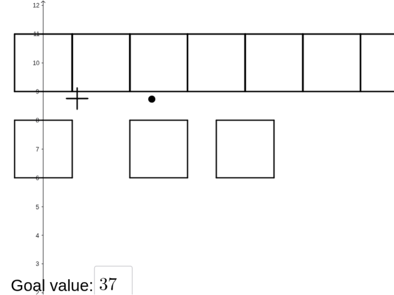
This example demonstrates how to use GeoGebra to build a polygon while simultaneously generating piecewise algebraic expressions and displaying them as formatted text. The visual effect is that geometric construction and symbolic expressions stay coordinated as conditions change. Key math concepts include algebraic expression creation, arithmetic with fractions, conditional logic via piecewise definitions (If), and connecting computed expression values to labeled geometric quantities (e.g., perimeter or selected lengths). Construction approach: Polygon is used to create the main polygon (poly* objects). If controls which expression branch is active, and Textfield provides parameters or user inputs that influence the expressions. FractionText converts fraction expressions into readable mathematical text, and text labeling objects annotate key results and intermediate values on the diagram using the relevant constructed points and derived quantities (e.g., objects like P or other labeled measures tied to the polygon). Suitable for middle and high school learners and for teaching activities involving piecewise functions, algebra-to-geometry modeling, and graph-free geometric reasoning with dynamic text and expressions.
GeoGebra Commands & Parameters
Polygon(A0, B, 4) → poly0, f, g, h, i, A, CPolygon(A3, H, 4) → poly3, j, k, l, m, E, GPolygon(A7, P, 4) → poly7, n, p, q, r, I, KPolygon(A1, D, 4) → poly1, s, t, a, b, M, OPolygon(A6, N, 4) → poly6, c, d, e, f_1, Q, SPolygon(A2, H2, 4) → poly2, k_1, l_1, m_1, n_1, W, ZPolygon(A8, A8 + (2, 0), 4) → poly8, g_1, h_1, i_1, j_1, U, VPolygon(A9, T, 4) → poly9, p_1, q_1, r_1, s_1, A_1, B_1Polygon(A4, J, 4) → poly4, t_1, a_1, b_1, c_1, C_1, D_1Polygon(A5, L, 4) → poly5, d_1, e_1, f_2, g_2, E_1, F_1Polygon(K_1, L_1, 4) → poly10, l_2, m_2, n_2, p_2, M_1, N_1Polygon(O_1, P_1, 4) → poly12, q_2, r_2, s_2, t_2, Q_1, R_1Polygon(S_1, T_1, 4) → poly13, a_2, b_2, c_2, d_2, U_1, V_1Polygon(C_2, D_2, 4) → poly15, i_3, j_3, k_3, l_3, E_2, F_2Polygon(G_2, H_2, 4) → poly16, m_3, n_3, p_3, q_3, I_2, J_2Polygon(G_{3}, H_{3}, 4) → poly17, m_{4}, n_{4}, p_{4}, q_{4}, I_{3}, J_{3}Polygon(C_{3}, D_{3}, 4) → poly14, i_{4}, j_{4}, k_{4}, l_{4}, E_{3}, F_{3}FractionText(u) → text4If(aleft > aright, "Left side is bigger.", aleft < aright, "Right side is bigger", "Both sides are equal!") → text9Textfield(w) → InputBox1If(o_1 < 0, "less than", o_1 > 0, "greater than", o_1 ≟ 0, "equal to") → text12
AI Drawing Prompt Reference
Create a dynamic geometry scene made of several congruent polygons placed in the same plane. Construct each polygon using the same number of sides, with different start vertices and corresponding control points so the polygons relate to one another by shared positions and adjacency. Alongside the geometry, show formatted algebra-related text that updates with conditions: include an input parameter, then display conditional messages based on comparing a left-side and a right-side expression, choosing among “Left side is bigger.”, “Right side is bigger”, or “Both sides are equal!”. Also add a second conditional label that changes based on whether another expression is less than 0, greater than 0, or equal to 0. Ensure the displayed conditions stay coordinated with the active geometric configuration.
The prompt above was compiled from the original drawing commands and is for reference only.