
Paper Model Animation
Loading the math board and drawing, please wait…
In collections
Action Modular Origami
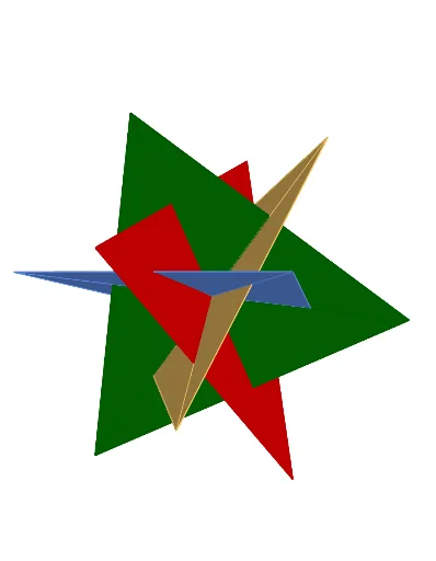
This example demonstrates the transformation of a paper model from the book 'Action Modular Origami' into a dynamic 3D model using GeoGebra. It involves core mathematical concepts such as solid geometry, vector operations, transformations, and polygon construction. Key GeoGebra commands and objects used in the construction include Line, OrthogonalPlane, Vector, Plane, Rotate, Translate, Midpoint, Dilate, Polygon, OrthogonalLine, Intersect, and Angle. It is suitable for high school students and mathematics enthusiasts to understand the principles of spatial geometry and dynamic transformations, serving as an example for teaching applications of solid geometry and vectors.
GeoGebra Commands & Parameters
Line(A, B) → lxOrthogonalPlane(B, lx) → xxVector(B, A) → uPlane(A, B, Bkeep) → zzRotate(A, (-(90°)), B, zz) → CTranslate(C, u) → DRotate(B, (-(90°)), C, xx) → GTranslate(G, u) → HRotate(C, 90°, B, xx) → FTranslate(F, u) → EMidpoint(C, G) → CGMidpoint(H, G) → GHMidpoint(F, G) → FGMidpoint(A, B) → ABMidpoint(A, E) → AEMidpoint(A, D) → ADMidpoint(B, F) → BFMidpoint(A, G) → ODilate(GH, b, O) → GH'Dilate(AD, b, O) → AD'Dilate(BF, b, O) → BF'Midpoint(D, H) → DHDilate(DH, b, O) → DH'Midpoint(E, H) → EHMidpoint(C, D) → CDMidpoint(B, C) → BCDilate(BC, b, O) → BC'Midpoint(E, F) → EFDilate(EF, b, O) → EF'Dilate(CD, b, O) → CD'Dilate(AE, b, O) → AE'Dilate(FG, b, O) → FG'Dilate(EH, b, O) → EH'Dilate(CG, b, O) → CG'Dilate(AB, b, O) → AB'Polygon(AE, BF, CG, DH) → poly1, i, j, k, lPolygon(AE', EF, FG', CG, CD', AD) → poly2, t, a_1, b_1, c_1, d_1, e_1Polygon(EH, EF', BF, BC', CD, DH') → poly4, f_1, g_1, h_1, i_1, j_1, k_1Polygon(GH', FG, BF', AB, AD', DH) → poly5, h, m, n, p, q, rPolygon(AB, EF, GH, CD) → poly1', i', j', k', l'Polygon(EH', GH, CG', BC, AB', AE) → poly3, c, d, e, f, g, sPolygon(AD, BC, FG, EH) → poly1'_1, i'_1, j'_1, k'_1, l'_1OrthogonalLine(A, zz) → lzPlane(A, B, F) → yyOrthogonalLine(A, yy) → l_1Line(O, lz) → lzzLine(O, lx) → lxxLine(O, l_1) → lyyRotate(GH, α, lzz) → GH'_1Rotate(FG, α, lzz) → FG'_1Rotate(EF, α, lzz) → EF'_1Rotate(EH, α, lzz) → EH'_1Polygon(GH', EH'_1, O) → poly6, o, gh', eh'_1Polygon(FG', GH'_1, O) → poly7, o_1, fg', gh'_1Polygon(EF', FG'_1, O) → poly8, o_2, ef', fg'_1Intersect(lyy, lzz) → IPolygon(EH', EF'_1, O) → poly9, o_3, eh', ef'_1Rotate(poly9, β, fg'_1) → poly9'Rotate(poly6, β, ef'_1) → poly6'Rotate(poly7, β, eh'_1) → poly7'Rotate(poly8, β, gh'_1) → poly8'Rotate(poly9, β, ef'_1) → poly9'_1Rotate(poly6, β, eh'_1) → poly6'_1Rotate(poly7, β, gh'_1) → poly7'_1Rotate(poly8, β, fg'_1) → poly8'_1Rotate(poly7, β, eh'_1) → poly7'_2Line(AE', CG') → aLine(DH', BF') → m_1Rotate(poly6', (-β), a) → poly6''Rotate(poly6'_1, β, a) → poly10Rotate(poly9'_1, β, m_1) → poly11Rotate(poly8', β, a) → poly8''Rotate(poly9', β, m_1) → poly9''OrthogonalLine(O, zz) → n_1Rotate(poly7', (-β), m_1) → poly7''Rotate(poly7'_1, β, m_1) → poly12Rotate(poly8'_1, (-β), a) → poly13Line(O, CD') → p_1Line(O, EH') → q_1Rotate(poly9'', (-β), q_1) → poly9'''Line(O, GH') → r_1Rotate(poly6'', (-β), r_1) → poly6'''Rotate(poly12, (-β), r_1) → poly12'Line(AD', O) → s_1Rotate(poly13, (-β), s_1) → poly13'Angle(O, EF', FG'_1, poly8'_1) → γRotate({poly10, poly6, poly6', poly6'', poly6''', poly6'_1}, spin, zAxis) → list1Rotate({poly11, poly9, poly9', poly9'', poly9''', poly9'_1}, spin, zAxis) → list2Rotate({poly13, poly13', poly8', poly8'', poly8, poly8'_1}, spin, zAxis) → list4Rotate({poly12, poly12', poly7, poly7', poly7'_2, poly7'_1, poly7''}, spin, zAxis) → list3
AI Drawing Prompt Reference
Draw a 3D origami-like geometric model composed of multiple triangular and quadrilateral faces, forming a symmetric polyhedral structure. Start with two base points, rotate one around the other in a perpendicular plane to create a new vertex, then translate it along the initial vector to get its counterpart. Repeat rotations and translations to generate a set of vertices. Connect these vertices to form polygons, including quadrilaterals and triangles. Take midpoints of edges, then dilate these midpoint segments toward the model's center by a scale factor to create inward crease effects. Finally, draw three reference lines from the center along orthogonal directions to indicate spatial orientation.
The prompt above was compiled from the original drawing commands and is for reference only.