
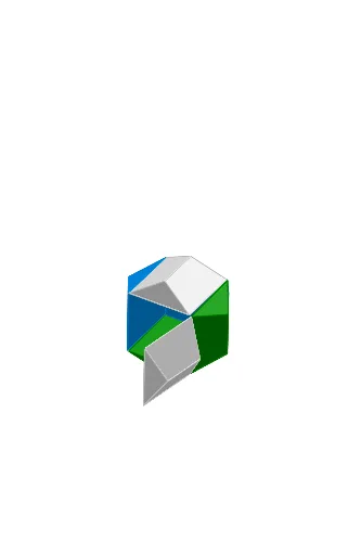
Cube – Regular Dodecahedron Origami Animation
Loading the math board and drawing, please wait…
In collections
Action Modular Origami
This example demonstrates an animated model of a cube and a regular dodecahedron folded from paper, showcasing the spatial relationships and transformations between polyhedra in solid geometry. The core mathematical concepts include regular polyhedra (cube, regular dodecahedron), rotation, symmetry, and three-dimensional geometric transformations. In terms of construction, the summary reveals the use of GeoGebra commands such as Point, Line, PolyLine, Segment, OrthogonalLine, Intersect, If, Plane, Polygon, Rotate, IntersectPath, and RoofPoly2, along with numerous objects like shift, K_1, T, S, m, g_1, D_2, h_1, Z_1, D_4, E_2, B_2, C_2, A_2, t, clock, rot1s, D, C, cc, A, C_1, B_1, A_1, Z, W, V, p, constClock, U, n, A1, rot1a, constSingle, rot0, bControl, rot1, J_1, I_1, G_1. Sliders control the rotation animation to simulate the folding process dynamically. This example is suitable for senior high school or early university students to understand properties of regular polyhedra, enhance spatial visualization, and learn GeoGebra 3D modeling and animation techniques.
GeoGebra Commands & Parameters
Point(xAxis) → SLine(S, T) → mLine(K_1, m) → g_1Line(D_2, m) → h_1Point(h_1) → B_2Point(h_1) → C_2Point(g_1) → A_2PolyLine(Z_1, A_2, B_2, C_2, D_4, E_2) → tSegment(C, D) → ccPoint(h_1) → A_1Point(h_1) → ZPoint(g_1) → WPolyLine(V, W, Z, A_1, B_1, C_1) → pOrthogonalLine(U, m) → nIntersect(n, p) → A1If(bControl ≟ constSingle, rot0, If[bControl ≟ constClock, rot1a, rot1s]) → rot1Point(h_1) → G_1Point(g_1) → F_1Point(t) → H_1PolyLine(E_1, F_1, G_1, H_1, I_1, J_1) → qIntersect(n, q) → A2Point(h_1) → O_1Point(h_1) → N_1Point(g_1) → M_1PolyLine(L_1, M_1, N_1, O_1, P_1, Q_1) → rIntersect(n, r) → A3Point(h_1) → U_1Point(h_1) → T_1Point(g_1) → S_1PolyLine(R_1, S_1, T_1, U_1, V_1, W_1) → sIntersect(n, s) → A4Intersect(n, t) → A5Segment(D, A) → ddPlane(B, C, D) → eSegment(A, B) → aaSegment(B, C) → bbIf(bControl ≟ constSingle, rot0, If[bControl ≟ constClock, rot4a, rot4s]) → rot4Polygon(A, B, C, D) → poly1, a, b, c, dRotate(B, (-rot1), cc) → B'Rotate(C, (-rot1), cc) → C'Rotate(D, (-rot1), cc) → D'Rotate(A, (-rot1), cc) → A'Polygon(A', B', C', D') → poly1', a', b', c', d'If(bControl ≟ constSingle, rot0, If[bControl ≟ constClock, rot2a, rot2s]) → rot2Rotate(poly1', rot2, b') → poly1''Rotate(D', rot2, b') → D''Rotate(A', rot2, b') → A''Segment(B', A'') → fIf(bControl ≟ constSingle, rot0, If[bControl ≟ constClock, rot3a, rot3s]) → rot3Rotate(poly1'', rot3, f) → poly1'''Rotate(D'', rot3, f) → D'''Rotate(C', rot3, f) → C'''Segment(A'', D''') → gRotate(poly1''', (-rot4), g) → poly2Rotate(C''', (-rot4), g) → C''''Rotate(B', (-rot4), g) → B'''Segment(D''', C'''') → hIf(bControl ≟ constSingle, rot0, If[bControl ≟ constClock, rot5a, rot5s]) → rot5Rotate(A'', rot5, h) → A'''Rotate(B''', rot5, h) → B''''Rotate(e, gable, dd) → e'_3Rotate(e, (-roof), aa) → e'_1IntersectPath(e'_3, e'_1) → iRotate(e, gable, bb) → e'IntersectPath(e', e'_1) → jRotate(e, (-roof), cc) → e'_2IntersectPath(e'_3, e'_2) → kIntersectPath(e', e'_2) → lIntersect(l, k) → EIntersect(j, i) → FRoofPoly2(A, B, C, D, gable, roof) → G, H, poly3, poly4, poly5, poly6, poly7RoofPoly2(A', D, C, B', gable, roof) → I, J, poly8, poly9, poly10, poly11, poly12RoofPoly2(C''', B', A'', D''', gable, roof) → K, L, poly13, poly14, poly15, poly16, poly17RoofPoly2(A''', D''', C'''', B'''', gable, roof) → M, N, poly18, poly19, poly20, poly21, poly22RoofPoly2(C, D'', A'', B', gable, roof) → O, P, poly23, poly24, poly25, poly26, poly27RoofPoly2(A'', B''', C'''', D''', gable, roof) → Q, R, poly28, poly29, poly30, poly31, poly32Line(D_1, m) → f_1
AI Drawing Prompt Reference
Create an animated model of a cube and a regular dodecahedron folded from paper, demonstrating spatial relationships and transformations between the polyhedra in solid geometry. The model simulates the folding process dynamically with rotation and symmetry, controlled by a slider. Begin by constructing basic geometric elements like points and lines, then form polygons and polylines, determine key positions using orthogonal lines and intersections, and finally achieve the final 3D model through rotations and transformations.
The prompt above was compiled from the original drawing commands and is for reference only.