
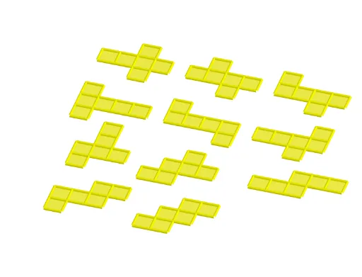
Nets of the Cube (11 Different Nets)
Loading the math board and drawing, please wait…
In collections
Geometry - Areas and Volumes
This example demonstrates 11 different nets of a cube, helping to understand the spatial geometry of how a 3D shape can be unfolded into a 2D plane. Using GeoGebra commands such as Cube, Rotate, Midpoint, etc., it visually shows the relative positions and connections of each face. Suitable for students at the junior high school level and above studying solid geometry.
GeoGebra Commands & Parameters
Cube(A, B, xOyPlane) → a, C, faceBCGF, faceCDHG, faceEFGH, edgeAD, edgeAB, edgeBC, edgeCD, edgeAE, edgeDH, edgeEH, D, edgeEF, edgeBF, edgeFG, edgeCG, edgeGH, E, F, G, H, faceABCD, faceADHE, faceABFERotate(faceABFE, (90° * t), edgeAB) → faceABFE'Midpoint(A, C) → IOrthogonalLine(I, xOyPlane) → bRotate(faceABFE', 90°, b) → faceABFE''Rotate(faceABFE', 180°, b) → faceABFE''_1Rotate(faceABFE', 270°, b) → faceABFE''_2Rotate(E, (90° * t), edgeAB) → E'Rotate(F, (90° * t), edgeAB) → F'Segment(E', F') → cRotate(Rotate[faceEFGH, (90° * t), edgeAB], (90° * t), Segment[E', F']) → poly1Translate(J, Vector[A, B]) → KTranslate(faceABFE''_1, Vector[A, J]) → poly2Translate(faceABCD, Vector[A, J]) → faceABCD'Translate(faceABFE', Vector[A, J]) → faceABFE''_3Translate(poly1, Vector[A, J]) → poly1'Translate(Rotate[Rotate[faceADHE, (90° * t), edgeAB], ((-(90°)) * t), Segment[Rotate[E, (90° * t), edgeAB], Rotate[A, (90° * t), edgeAB]]], Vector[A, J]) → poly4Translate(faceABFE'', Vector[A, J]) → faceABFE'''Translate(faceABCD, Vector[A, L]) → faceABCD'_1Translate(faceABFE''_1, Vector[A, L]) → poly3Translate(faceABFE', Vector[A, L]) → faceABFE''_4Translate(poly1, Vector[A, L]) → poly1'_1Translate(faceABFE'', Vector[A, L]) → faceABFE'''_1Midpoint(B, E') → MOrthogonalLine(M, faceABFE') → dTranslate(Rotate[faceABFE'', 180°, d], Vector[A, L]) → poly5Translate(faceABCD, Vector[A, O]) → faceABCD'_2Translate(faceABFE''_1, Vector[A, O]) → poly6Translate(faceABFE', Vector[A, O]) → faceABFE''_5Translate(poly1, Vector[A, O]) → poly1'_2Translate(faceABFE'', Vector[A, O]) → faceABFE'''_2Translate(Rotate[Rotate[faceADHE, (90° * t), edgeCD], (90° * t), Segment[Rotate[H, (90° * t), edgeCD], Rotate[D, (90° * t), edgeCD]]], Vector[A, O]) → poly8Translate(faceABCD, Vector[A, N]) → faceABCD'_3Translate(faceABFE''_1, Vector[A, N]) → poly7Translate(faceABFE', Vector[A, N]) → faceABFE''_6Translate(poly1, Vector[A, N]) → poly1'_3Translate(Rotate[faceABFE'', 180°, d], Vector[A, N]) → poly9Rotate(Rotate[H, (90° * t), edgeAB], (90° * t), Segment[E', F']) → PMidpoint(P, F') → QOrthogonalLine(Q, poly1) → eTranslate(Rotate[Rotate[faceABFE'', 180°, d], 180°, e], Vector[A, N]) → poly10Translate(faceABCD, Vector[A, R]) → faceABCD'_4Translate(faceABFE''_1, Vector[A, R]) → poly11Translate(faceABFE', Vector[A, R]) → faceABFE''_7Translate(poly1, Vector[A, R]) → poly1'_4Translate(Rotate[faceABFE'', 180°, d], Vector[A, R]) → poly12Rotate(F', 180°, b) → F''Midpoint(C, F'') → SOrthogonalLine(S, faceABFE''_1) → gTranslate(Rotate[Rotate[Rotate[faceADHE, (90° * t), edgeCD], (90° * t), Segment[Rotate[H, (90° * t), edgeCD], Rotate[D, (90° * t), edgeCD]]], 180°, g], Vector[A, R]) → poly15Translate(faceABCD, Vector[A, T]) → faceABCD'_5Translate(faceABFE''_1, Vector[A, T]) → poly13Translate(faceABFE', Vector[A, T]) → faceABFE''_8Translate(Rotate[faceABFE', 270°, b], Vector[A, T]) → poly14Translate(Rotate[poly1, (-(90°)), b], Vector[A, T]) → poly16Translate(Rotate[Rotate[Rotate[faceADHE, (90° * t), edgeAB], ((-(90°)) * t), Segment[Rotate[E, (90° * t), edgeAB], Rotate[A, (90° * t), edgeAB]]], 180°, d], Vector[A, T]) → poly17Translate(faceABCD, Vector[A, U]) → faceABCD'_6Translate(faceABFE''_1, Vector[A, U]) → poly18Translate(faceABFE', Vector[A, U]) → faceABFE''_9Translate(Rotate[faceABFE', 270°, b], Vector[A, U]) → poly19Translate(Rotate[Rotate[Rotate[faceADHE, (90° * t), edgeAB], ((-(90°)) * t), Segment[Rotate[E, (90° * t), edgeAB], Rotate[A, (90° * t), edgeAB]]], 180°, d], Vector[A, U]) → poly20Translate(Rotate[faceABFE'', 270°, d], Vector[A, U]) → poly22Translate(faceABCD, Vector[A, V]) → faceABCD'_7Translate(faceABFE''_1, Vector[A, V]) → poly21Translate(Rotate[faceABFE, (90° * t), edgeAB], Vector[A, V]) → poly23Translate(Rotate[Rotate[faceADHE, (90° * t), edgeCD], (90° * t), Segment[Rotate[H, (90° * t), edgeCD], Rotate[D, (90° * t), edgeCD]]], Vector[A, V]) → poly24Rotate(Rotate[faceADHE, (90° * t), edgeCD], (90° * t), Segment[Rotate[H, (90° * t), edgeCD], Rotate[D, (90° * t), edgeCD]]) → poly25Rotate(Rotate[E, (90° * t), edgeCD], (90° * t), Segment[Rotate[H, (90° * t), edgeCD], Rotate[D, (90° * t), edgeCD]]) → WMidpoint(D, W) → ZOrthogonalLine(Z, poly25) → hRotate(faceABFE''_1, 90°, h) → poly26Translate(Rotate[faceABFE''_1, 90°, h], Vector[A, V]) → poly27Rotate(C, 90°, h) → C'Midpoint(W, C') → A_1OrthogonalLine(A_1, poly26) → iRotate(poly25, 180°, i) → poly25'Translate(Rotate[poly25, 180°, i], Vector[A, V]) → poly28Translate(faceABCD, Vector[A, B_1]) → faceABCD'_8Translate(faceABFE''_1, Vector[A, B_1]) → poly29Translate(faceABFE', Vector[A, B_1]) → faceABFE''_{10}Translate(Rotate[Rotate[Rotate[faceADHE, (90° * t), edgeAB], ((-(90°)) * t), Segment[Rotate[E, (90° * t), edgeAB], Rotate[A, (90° * t), edgeAB]]], 180°, d], Vector[A, B_1]) → poly30Translate(Rotate[Rotate[faceADHE, (90° * t), edgeCD], (90° * t), Segment[Rotate[H, (90° * t), edgeCD], Rotate[D, (90° * t), edgeCD]]], Vector[A, B_1]) → poly31Translate(Rotate[faceABFE''_1, 90°, h], Vector[A, B_1]) → poly32Translate(faceABCD, Vector[A, C_1]) → faceABCD'_9Translate(faceABFE''_1, Vector[A, C_1]) → poly33Translate(Rotate[Rotate[faceADHE, (90° * t), edgeCD], (90° * t), Segment[Rotate[H, (90° * t), edgeCD], Rotate[D, (90° * t), edgeCD]]], Vector[A, C_1]) → poly34Translate(Rotate[faceABFE''_1, 90°, h], Vector[A, C_1]) → poly35Translate(faceABFE'', Vector[A, C_1]) → faceABFE'''_3Rotate(G, 90°, b) → G'Rotate(F', 90°, b) → F''_1Midpoint(B, F''_1) → D_1OrthogonalLine(D_1, faceABFE'') → jRotate(faceABCD, 90°, j) → faceABCD'_{10}Translate(Rotate[faceABCD, 90°, j], Vector[A, C_1]) → poly36
AI Drawing Prompt Reference
Draw 11 different nets of a cube, showing how a 3D cube can be unfolded into a 2D plane. Start by creating a cube, then use rotation and reflection to generate multiple nets, each consisting of 6 connected square faces. Use distinct colors or line styles to differentiate the faces and edges, making it easy to observe the structure and folding patterns of each net.
The prompt above was compiled from the original drawing commands and is for reference only.