
Net of a Cone by พรหมลิขิต จิตจักร
Loading the math board and drawing, please wait…
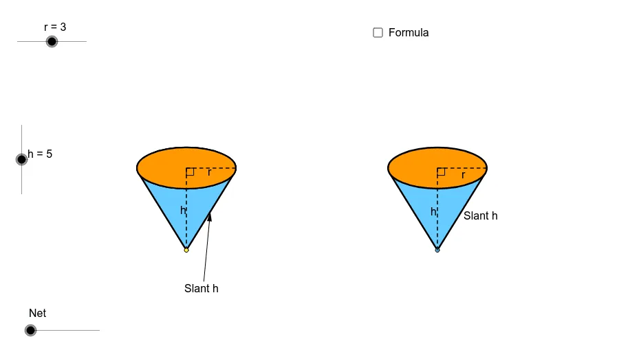
This example demonstrates the net of a cone and shows the process of generating a cone through animation. Key mathematical concepts include solid geometry and geometric construction. It uses commands such as Point, Circle, Intersect, Ellipse, Vector, Translate, Arc, Segment, Angle, Line, Midpoint, If, Conic, OrthogonalLine, Tangent, Rotate, Center, Mirror, Polygon, CircleSector. Suitable for middle and high school students learning solid geometry and geometric construction.
GeoGebra Commands & Parameters
Point(xAxis) → ACircle(A, r) → cIntersect(c, xAxis) → B, CEllipse(E, D, C) → eIntersect(xAxis, yAxis) → FVector(F, G) → uTranslate(B, Vector[u * h]) → B'_1Translate(C, Vector[u * h]) → C'_1Translate(A, Vector[u * h]) → A'_1Translate(e, Vector[u * h]) → e'_1Arc(e'_1, C'_1, B'_1) → p_5Arc(e'_1, B'_1, C'_1) → qSegment(A'_1, A) → h_6Segment(A'_1, C'_1) → pAngle(A, A'_1, C'_1) → αLine(A, A'_1) → jIntersect(e'_1, j) → H, ICircle(I, r) → tIntersect(t, j, 2.0) → KCircle(K, I) → d_1Intersect(d_1, j, 2.0) → NVector(H, N) → vTranslate(H, Vector[v * n]) → H'_1Translate(D, Vector[u * h]) → D'Translate(E, Vector[u * h]) → E'Line(B, B'_1) → lLine(C, C'_1) → mIntersect(d_1, l, 1.0) → PIntersect(d_1, m, 1.0) → QVector(B'_1, P) → zVector(C'_1, Q) → u_1Translate(B'_1, Vector[z * n]) → B''Translate(C'_1, Vector[u_1 * n]) → C''Midpoint(B'_1, A'_1) → RMidpoint(B, A) → SLine(R, S) → a_1Intersect(q, a_1) → T,Intersect(d_1, a_1, 1.0) → UVector(T, U) → v_1Translate(T, Vector[v_1 * n]) → T'If(n < 1.0, B'', P) → B_1If(n < 1.0, T', U) → D_1If(n < 1.0, H'_1, N) → E_1If(n < 1.0, C'', Q) → F_1Conic(B_1, D_1, E_1, F_1, I) → g_1Conic(I, B_1, D_1, E_1, F_1) → h_1OrthogonalLine(I, j) → l_1OrthogonalLine(H, j) → b_2Intersect(m, l_1) → H_2Midpoint(H_2, C'_1) → I_2OrthogonalLine(C'_1, m) → i_2Segment(K, F_1) → m_4Translate(e, Vector[u * h]) → e'Tangent(A, e'_1) → a, bIntersect(e', b) → J, G_2Intersect(e', a) → L, R_2Segment(A, J) → fSegment(A, L) → gCircle(I, sqrt(h^(2.0) + r^(2.0))) → kIntersect(k, j, 1.0) → MCircle(M, sqrt(h^(2.0) + r^(2.0))) → sSegment(M, I) → iRotate(I, γ, M) → I'_1Rotate(I, -(γ), M) → I'_2OrthogonalLine(I'_2, i_2) → b_1Intersect(b_2, b_1) → OMidpoint(H, O) → VCircle(V, O) → c_1Vector(O, I'_2) → wCenter(g_1) → WSegment(W, F_1) → e_1Vector(H, A) → w_1Translate(H, Vector[w_1 * (n - 1.0)]) → H'If(n < 1.0, H, If[n < 2.0, H', A]) → ZSegment(H, Z) → f_1Rotate(I, -(δ), M) → I'Vector(L, I') → z_1Translate(c_1, Vector[w * (n - 2.0)]) → k_1Center(k_1) → A_1Intersect(k_1, j) → C_1, Q_1Rotate(C_1, 180.0° * (n - 2.0), A_1) → G_1If(n < 2.0, H, If[n ≤ 3.0, G_1, I'_2]) → H_1Mirror(H_1, j) → I_1Translate(L, Vector[z_1 * (n - 2.0)]) → L'If(n < 2.0, L, If[n ≤ 3.0, L', I']) → J_1Mirror(J_1, j) → K_1Conic(I_1, H_1, J_1, I, K_1) → p_1Vector(A, M) → i_1Translate(A, Vector[i_1 * (n - 2.0)]) → A'If(n < 2.0, A, If[n ≤ 3.0, A', M]) → L_1Tangent(L_1, p_1) → j_1, m_1Intersect(p_1, m_1, 1.0) → M_1Intersect(p_1, j_1, 1.0) → N_1Polygon(L_1, M_1, N_1) → poly1, n_1, l_2, m_2Arc(p_1, N_1, M_1) → q_1Line(L_1, b_2) → r_1Intersect(p_1, r_1, 1.0) → O_1Intersect(p_1, r_1, 2.0) → P_1Arc(p_1, P_1, O_1) → s_1Polygon(L_1, O_1, I_1) → poly2, i_3, l_3, o_1Polygon(L_1, H_1, P_1) → poly3, p_2, l_4, h_2Arc(p_1, O_1, I_1) → t_1Arc(p_1, H_1, P_1) → c_2Segment(L_1, I_1) → a_2Segment(L_1, H_1) → d_2Arc(p_1, H_1, I_1) → e_2Polygon(I_1, L_1, H_1) → poly4, h_3, i_4, l_5CircleSector(M, I'_2, I'_1) → f_2CircleSector(M, I'_2, I'_1) → g_2Arc(p_1, H_1, I_1) → k_2Segment(M_1, L_1) → j_2Segment(N_1, L_1) → n_2Polygon(I_1, L_1, H_1) → poly5, h_4, i_5, l_6Arc(p_1, H_1, I_1) → q_2Polygon(J, A, L) → poly6, l_7, j_3, a_3Point(xAxis) → R_1OrthogonalLine(R_1, xAxis) → r_2Intersect(i_2, r_2) → S_1Circle(R_1, r) → s_2Intersect(s_2, xAxis) → T_1, U_1OrthogonalLine(T_1, i_2) → t_2OrthogonalLine(V_1, i_2) → b_3OrthogonalLine(W_1, i_2) → c_3Intersect(i_2, t_2) → Z_1Intersect(i_2, b_3) → A_2Intersect(i_2, c_3) → B_2Ellipse(A_2, B_2, Z_1) → d_3Tangent(R_1, d_3) → e_3, f_3Intersect(d_3, f_3, 1.0) → C_2Intersect(d_3, e_3, 1.0) → D_2Polygon(C_2, D_2, R_1) → poly7, r_3, c_4, d_4Ellipse(A_2, B_2, Z_1) → g_3OrthogonalLine(U_1, xAxis) → k_3Intersect(g_3, k_3) → E_2, J_2Segment(S_1, E_2) → m_3Segment(S_1, R_1) → n_3Intersect(d_3, m_3, 1.0) → F_2Midpoint(g) → K_2Midpoint(f_1) → L_2Point(j) → M_2Midpoint(I_1, A') → N_2Midpoint(A', H_1) → O_2Vector(M_2, N_2) → u_2Vector(M_2, O_2) → v_2Line(M_2, r_1) → p_3Point(p_3) → P_2Vector(P_2, K_2) → z_2Vector(P_2, L_2) → u_3Center(g_3) → Q_2Angle(F_2, Q_2, R_1) → εSegment(I_1, H_1) → q_3Intersect(k_2, q_3, 2.0) → S_2
AI Drawing Prompt Reference
Draw the net of a cone, showing its lateral surface as a sector and its base as a circle. Start by drawing the base circle and the apex of the cone, then create the sector representing the lateral surface. Use rotation and reflection to combine the sector and base into the net of the cone. Add some guide lines and angle markings to illustrate the geometric construction process.
The prompt above was compiled from the original drawing commands and is for reference only.