
Multilevel Experiment Design and Data Analysis
Loading the math board and drawing, please wait…
In collections
Complex Math
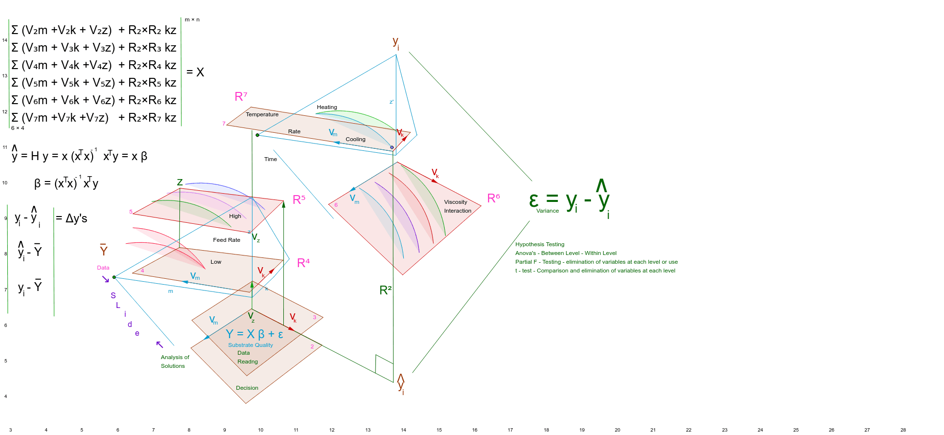
This example demonstrates the setup of a multilevel experiment and its data analysis process. It involves core mathematical concepts such as linear algebra in Rn space, geometric constructions, and transformations. Key GeoGebra commands and objects used include Line, Point, Circle, Segment, OrthogonalLine, Polygon, Vector, Translate, Intersect, LaTeX, CircleArc, and Rotate, as outlined in the construction summary. It is suitable for high school and above students to understand the practical application of experimental design and spatial linear algebra.
GeoGebra Commands & Parameters
Line(A, B) → aPoint(a) → CCircle(C, D) → cSegment(C, D) → bLine(E, xAxis) → dOrthogonalLine(F, d) → eLine(G, e) → fLine(H, d) → gLine(I, b) → hPoint(f) → JPoint(d) → LPoint(c) → KSegment(D, J) → iSegment(J, K) → jSegment(K, L) → kSegment(L, D) → zSegment(L, C) → mPolygon(M, N, O, P) → poly1, m_1, n, o, pPolygon(Q, R, S, T) → poly2, q, r, s, tPolygon(U, V, W) → poly3, w, u, vPolygon(Z, A_1, B_1) → poly4, b_1, z_1, a_1Vector(C_1, D_1) → u_1Translate(Z, u_1) → Z'Translate(A_1, u_1) → E_1Translate(B_1, u_1) → F_1Vector(G_1, H_1) → v_1Translate(U, v_1) → U'Translate(V, v_1) → V'Translate(W, v_1) → W'Polygon(U', V', W') → poly3', w', u', v'Intersect(b, i) → I_1Intersect(i, j) → L_1Intersect(k, z) → N_1Intersect(k, z) → J_1Segment(J_1, K_1) → c_1Segment(C, M_1) → d_1Segment(K_1, M_1) → e_1Segment(O_1, K_1) → f_1Segment(O_1, P_1) → g_1Segment(P_1, M_1) → h_1Point(f_1) → Q_1Point(h_1) → R_1Segment(Q_1, R_1) → i_1Point(k) → S_1Point(m) → T_1Point(m_1) → W_1Point(m_1) → Z_1Vector(W_1, Z_1) → w_1Point(r) → A_2Point(r) → B_2Vector(A_2, B_2) → j_1Polygon(M_2, N_2, O_2, P_2) → poly1_1, m_2, n_1, o_1, p_1Point(m_2) → W_2Point(m_2) → Z_2Polygon(M_3, N_3, O_3, P_3) → poly1_2, m_3, n_2, o_2, p_2Point(m_3) → W_3Point(m_3) → Z_3Polygon(M_4, N_4, O_4, P_4) → poly1_3, m_4, n_3, o_3, p_3Point(m_4) → W_4Point(m_4) → Z_4Point(q) → C_2Point(q) → D_2Vector(C_2, D_2) → k_1Point(n) → E_2Point(n) → F_2Vector(E_2, F_2) → l_1Intersect(m_1, n) → G_2Vector(G_2, H_2) → lVector(I_2, J_2) → q_1Vector(K_2, L_2) → r_1Translate(Q, r_1) → Q'Translate(R, r_1) → R'Translate(S, r_1) → S'Translate(T, r_1) → T'Polygon(Q', R', S', T') → poly2', q', r', s', t'Vector(Q_2, R_2) → s_1Translate(M, s_1) → M'Translate(N, s_1) → N'Translate(O, s_1) → O'Translate(P, s_1) → P'Polygon(M', N', O', P') → poly1', m', n', o', p'Intersect(o', p') → S_2Intersect(o, p) → T_2Segment(S_2, T_2) → t_1Vector(U_2, V_2) → u_2Translate(O_1, u_2) → A_3Translate(P_1, u_2) → B_3Segment(A_3, B_3) → a_2Vector(C_3, D_3) → v_2Translate(C, v_2) → C'Intersect(m', p') → E_3Point(r) → F_3Segment(E_3, F_3) → b_2Point(r) → G_3Intersect(m', p') → H_3Vector(G_3, H_3) → w_2Vector(I_3, J_3) → c_2Translate(K, c_2) → K'Translate(L, c_2) → L'Segment(K', L') → k'Vector(K_3, L_3) → d_2Translate(L, d_2) → L'_1Translate(C, d_2) → C'_1Segment(L'_1, C'_1) → m'_1Vector(Q_3, R_3) → e_2Translate(A_3, e_2) → S_3Translate(B_3, e_2) → T_3Segment(S_3, T_3) → f_2Polygon(U_3, V_3, A_4, B_4) → poly5, u_3, v_3, a_4, b_4Vector(G_4, H_4) → g_2Translate(L, g_2) → L'_2Translate(D, g_2) → D'Segment(L'_2, D') → z'Vector(I_4, J_4) → h_2Translate(J, h_2) → J'Translate(K, h_2) → K'_1Segment(J', K'_1) → j'Vector(K_4, L_4) → i_2Translate(C, i_2) → C'_2Translate(D, i_2) → D'_1Segment(C'_2, D'_1) → b'Point(k') → Q_4Point(z') → R_4Segment(Q_4, R_4) → j_2Polygon(S_4, T_4, U_4, V_4) → poly6, s_4, t_4, u_4, v_4Intersect(u_3, b_4) → A_5Segment(A_5, B_5) → k_2Intersect(q, r) → C_5Segment(B_5, C_5) → l_2Point(k_2) → D_5Segment(D_5, E_5) → q_2Point(l_2) → F_5Segment(E_5, F_5) → r_2Intersect(b, i) → G_5Segment(G_5, H_5) → s_2Intersect(s_4, v_4) → I_5Point(v_4) → J_5Vector(I_5, J_5) → t_2Intersect(u_3, b_4) → K_5Point(b_4) → L_5Vector(K_5, L_5) → w_3Intersect(u_3, b_4) → M_5Point(u_3) → N_5Vector(M_5, N_5) → a_3Intersect(s_4, v_4) → O_5Point(s_4) → P_5Vector(O_5, P_5) → b_3LaTeX(a_3, true, true) → text7Vector(Q_5, R_5) → c_3Translate(L'_1, c_3) → S_5Vector(U_5, V_5) → e_3Translate(K', e_3) → K''Translate(L', e_3) → L''CircleArc(C, T_5, G_6) → d_3Translate(d_3, Vector[(0, 0.01366026910730156)]) → f_3Vector(J_6, K_6) → g_3Translate(d_3, g_3) → h_3Line(A_7, B_7) → a_5Point(a_5) → C_7CircleArc(C_7, T_6, G_7) → d_4Vector(J_7, K_7) → g_4Line(A_8, B_8) → a_6Point(a_6) → C_8CircleArc(C_8, T_7, G_8) → d_5Vector(J_8, K_8) → g_5Vector(L_6, M_6) → j_3Translate(d_3, j_3) → k_3Vector(N_6, O_6) → l_3Translate(d_3, l_3) → q_3Vector(P_6, R_6) → r_3Translate(d_3, r_3) → s_3Vector(S_6, V_6) → t_3Translate(d_3, t_3) → c_4Point(c_4) → W_6Rotate(c_4, 45*°, W_6) → e_4Vector(Z_6, D_7) → w_4Translate(d_3, w_4) → f_4Vector(E_7, F_7) → h_4Translate(d_3, h_4) → k_4Vector(H_7, I_7) → i_4Translate(d_3, i_4) → p_4Point(p_4) → L_7Point(k_4) → M_7Point(f_4) → N_7Rotate(p_4, 30*°, L_7) → q_4Rotate(p_4, 15*°, L_7) → r_4Rotate(p_4, 40*°, L_7) → c_5Rotate(f_4, 40*°, N_7) → e_5Rotate(k_4, 40*°, M_7) → f_5Point(d_3) → O_7Rotate(d_3, 40*°, O_7) → h_5Rotate(d_3, 28*°, O_7) → k_5Vector(P_7, Q_7) → j_4Translate(s_3, j_4) → p_5Point(p_5) → R_7Rotate(p_5, 34*°, R_7) → q_5Segment(U_7, V_7) → l_4Segment(U_8, V_8) → l_5Segment(W_7, Z_7) → n_4Segment(D_8, E_8) → b_5Segment(U_9, V_9) → l_6Segment(U_{10}, V_{10}) → l_7
AI Drawing Prompt Reference
Draw a geometric representation of multilevel experiment design and data analysis, including lines, points, circles, segments, orthogonal lines, polygons, and vectors. Start by constructing a basic shape with a circle and two intersecting lines, then generate multiple polygons through rotations and translations to demonstrate the application of linear algebra and geometric transformations. Finally, connect key points to form closed polygons and use segments and vectors to represent spatial relationships.
The prompt above was compiled from the original drawing commands and is for reference only.