
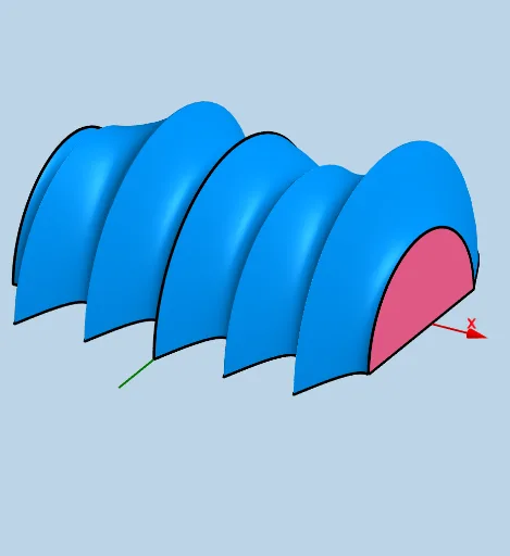
Modifiable Solid with Semicircular Cross Sections Parallel to yAxis
Loading the math board and drawing, please wait…
This example demonstrates constructing a modifiable solid with semicircular cross sections parallel to the yAxis. Key mathematical concepts include integral calculus and solid geometry. Using GeoGebra commands such as CurveCartesian, Surface, and Rotate, the relationship between the cross-sectional shape and the overall solid's volume is visually illustrated. Suitable for high school and above students studying solid geometry and calculus.
GeoGebra Commands & Parameters
Segment(H, I) → s_1Midpoint(s_1) → ESegment(J, K) → q_1Midpoint(q_1) → FIntersect(upper, h, (0, 5)) → BIntersect(lower, h, (0, -8)) → CSegment(C, B) → qIntersect(upper, q, (0, 5)) → GMidpoint(C, G) → TLine(B, D) → iSphere(B, d) → eSegment(C, B) → pTextfield(upper) → InputBox1Textfield(lower) → InputBox2Textfield(a) → InputBox3Textfield(b) → InputBox4Segment(C, G) → k_1Midpoint(J, K) → ZMidpoint(Q, P) → A_1CurveCartesian(b, y(Z) + ((y(J) - y(Z)) * cos(u)), ((y(J) - y(Z)) * sin(u)), u, 0, pi) → fCurveCartesian(a, y(A_1) + ((y(Q) - y(A_1)) * cos(u)), ((y(Q) - y(A_1)) * sin(u)), u, 0, pi) → cSurface(u, (0.5 * (upper(u) + lower(u))) + ((0.5 * (upper(u) - lower(u))) * cos(v)), ((0.5 * (upper(u) - lower(u))) * sin(v)), u, a, b, v, 0, pi) → gMidpoint(C, G) → WCurveCartesian(x(W), (0.5 * (y(G) + y(C))) + ((0.5 * (y(G) - y(C))) * cos(u)), ((0.5 * (y(G) - y(C))) * sin(u)), u, 0, pi) → jLine(W, B_1) → kSphere(W, G) → lIntersect(k, l) → C_1, D_1Rotate(D_1, ((-pi)) / 2, W) → E_1Rotate(D_1, pi / 2, W) → F_1CircleArc(W, E_1, F_1, xOyPlane) → rLine(W, E_1) → mRotate(r, pi / 2, W, m) → r'Midpoint(q_1) → G_1Midpoint(s_1) → H_1Line(G_1, G_1 + (1, 0, 0)) → nLine(H_1, H_1 + (1, 0, 0)) → sSphere(G_1, J) → oIntersect(n, o) → I_1, J_1Sphere(H_1, Q) → tIntersect(s, t) → K_1, L_1Rotate(J_1, ((-pi)) / 2, G_1) → M_1Rotate(J_1, pi / 2, G_1) → N_1CircleArc(G_1, M_1, N_1, xOyPlane) → c_1Rotate(c_1, ((-pi)) / 2, G_1, Line[G_1, N_1]) → e_1Rotate(L_1, ((-pi)) / 2, H_1) → O_1Rotate(L_1, pi / 2, H_1) → P_1CircleArc(H_1, O_1, P_1, xOyPlane) → d_1Rotate(d_1, ((-pi)) / 2, H_1, Line[H_1, Q]) → f_1