
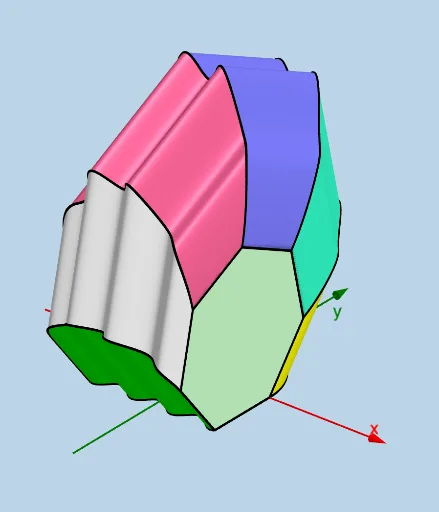
Modifiable Solid: Regular Heptagon Cross Sections Parallel to yAxis
Loading the math board and drawing, please wait…
This example demonstrates a modifiable solid where cross sections parallel to the yAxis are regular heptagons. Core math concepts include integral calculus and polygon construction in geometry. Construction highlights involve GeoGebra commands like Segment, Midpoint, Line, Rotate, Intersect, Polygon, etc., to create cross-sections. Suitable for high school and above students to explore the integration of solid geometry and calculus.
GeoGebra Commands & Parameters
Segment(H, I) → s_1Midpoint(s_1) → A_1Line(H_1, H_1 - (1, 0, 0)) → l_1Rotate(I, (2 * pi / 7), H_1, l_1) → I'Rotate(I', (2 * pi / 7), H_1, l_1) → I''Rotate(I'', (2 * pi / 7), H_1, l_1) → I'''Rotate(I''', (2 * pi / 7), H_1, l_1) → I_1Rotate(I_1, (2 * pi / 7), H_1, l_1) → L_1Segment(J, K) → q_1Midpoint(q_1) → ZLine(D_1, D_1 + (1, 0, 0)) → gRotate(J, (2 * pi / 7), D_1, g) → J'Rotate(J', (2 * pi / 7), D_1, g) → J''Rotate(J'', (2 * pi / 7), D_1, g) → J'''Rotate(J''', (2 * pi / 7), D_1, g) → E_1Rotate(E_1, (2 * pi / 7), D_1, g) → K_1Intersect(lower, h, (-10, -10.839071529076453)) → CIntersect(upper, h, (-10, 0)) → BSegment(C, B) → qIntersect(upper, q, (-10, 0)) → GMidpoint(C, G) → TLine(T, T + (1, 0, 0)) → mLine(F_1, F_1 + (1, 0, 0)) → nRotate(G, (2 * pi / 7), F_1, n) → G'Rotate(G', (2 * pi / 7), F_1, n) → G''Rotate(G'', (2 * pi / 7), F_1, n) → G'''Rotate(G''', (2 * pi / 7), F_1, n) → G_1Rotate(G_1, (2 * pi / 7), F_1, n) → J_1Midpoint(s_1) → EMidpoint(q_1) → FLine(B, D) → iSphere(B, d) → eSegment(C, B) → pTextfield(upper) → InputBox1Textfield(lower) → InputBox2Textfield(a) → InputBox3Textfield(b) → InputBox4Segment(C, G) → k_1Line(C, G) → jPolygon(C, G, G', G'', G''', G_1, J_1) → poly1, m_1, r_1, a_1, b_1, c_1, d_1, f_2Sphere(G, T) → kSegment(G', G'') → lSegment(G'', G''') → rSegment(G''', G_1) → sSegment(G', G) → i_1Line(Z, Z + (1, 0, 0)) → fSegment(J, J') → f_1Polygon(H, I, I', I'', I''', I_1, L_1) → poly2, h_2, i_2, s_2, t_2, a_2, b_2, c_2Polygon(K, J, J', J'', J''', E_1, K_1) → poly3, g_1, j_1, n_1, p_1, e_1, j_2, k_2Segment(G_1, J_1) → g_2Segment(J_1, C) → l_2Segment(J', J'') → m_2Segment(J'', J''') → n_2Segment(J''', E_1) → p_2Segment(E_1, K_1) → q_2Segment(K_1, K) → r_2Segment(I', I) → d_2Segment(I', I'') → e_2Segment(I'', I''') → f_3Segment(I''', I_1) → g_3Segment(I_1, L_1) → h_3Segment(L_1, H) → i_3CurveCartesian(t, lower(t) - (cos((2 * pi / 7)) * (upper(t) - lower(t))), (sin((2 * pi / 7)) * (upper(t) - lower(t))), t, a, b) → o_2CurveCartesian(t, upper(t) + (cos((2 * pi / 7)) * (upper(t) - lower(t))), (sin((2 * pi / 7)) * (upper(t) - lower(t))), t, a, b) → cCurveCartesian(t, (0.5 * (upper(t) + lower(t))), ((0.5 * tan((5 * pi / 14))) * (upper(t) - lower(t))) + (0.5 * (upper(t) - lower(t)) / cos((5 * pi / 14))), t, a, b) → vCurveCartesian(t, ((-(upper(t) - lower(t))) * sin((5 * pi / 14))) + (0.5 * (upper(t) + lower(t))), ((0.5 * (upper(t) - lower(t))) * tan((5 * pi / 14))) + (0.5 * (upper(t) - lower(t)) / cos((5 * pi / 14))) - ((upper(t) - lower(t)) * cos((5 * pi / 14))), t, a, b) → tCurveCartesian(t, ((upper(t) - lower(t)) * sin((5 * pi / 14))) + (0.5 * (upper(t) + lower(t))), ((0.5 * (upper(t) - lower(t))) * tan((5 * pi / 14))) + (0.5 * (upper(t) - lower(t)) / cos((5 * pi / 14))) - ((upper(t) - lower(t)) * cos((5 * pi / 14))), t, a, b) → wSurface(u, lower(u) - ((v * cos((2 * pi / 7))) * (upper(u) - lower(u))), ((v * sin((2 * pi / 7))) * (upper(u) - lower(u))), u, a, b, v, 0, 1) → oSurface(u, upper(u) + (v * (cos((2 * pi / 7)) * (upper(u) - lower(u)))), ((v * sin((2 * pi / 7))) * (upper(u) - lower(u))), u, a, b, v, 0, 1) → uSurface(u, lower(u) - ((upper(u) - lower(u)) * cos((2 * pi / 7))) + ((v * (upper(u) - lower(u))) * sin(pi / 14)), ((upper(u) - lower(u)) * sin((2 * pi / 7))) + ((v * (upper(u) - lower(u))) * cos(pi / 14)), u, a, b, v, 0, 1) → o_1Surface(u, upper(u) + ((upper(u) - lower(u)) * cos((2 * pi / 7))) - ((v * (upper(u) - lower(u))) * sin(pi / 14)), ((upper(u) - lower(u)) * sin((2 * pi / 7))) + ((v * (upper(u) - lower(u))) * cos(pi / 14)), u, a, b, v, 0, 1) → u_1Surface(u, lower(u) - ((upper(u) - lower(u)) * (cos((2 * pi / 7)) - sin(pi / 14))) + (v * ((0.5 * (upper(u) + lower(u))) - (lower(u) - ((upper(u) - lower(u)) * (cos((2 * pi / 7)) - sin(pi / 14)))))), ((upper(u) - lower(u)) * (sin((2 * pi / 7)) + cos(pi / 14))) + ((v * (upper(u) - lower(u))) * cos((5 * pi / 14))), u, a, b, v, 0, 1) → u_2Surface(u, (0.5 * (upper(u) + lower(u))) + ((v * (upper(u) - lower(u))) * sin((5 * pi / 14))), ((0.5 * (upper(u) - lower(u))) * tan((5 * pi / 14))) + ((upper(u) - lower(u)) * sin((5 * pi / 14)) / tan((2 * pi / 7))) + (((1 - v) * (upper(u) - lower(u))) * cos((5 * pi / 14))), u, a, b, v, 0, 1) → v_2
AI Drawing Prompt Reference
Draw a modifiable solid with regular heptagon cross sections parallel to the yAxis. First, create two parallel heptagon cross sections to the yAxis and use rotation to generate a series of heptagons, forming one solid. Then, create another heptagon cross section parallel to the yAxis and use rotation to generate another series of heptagons, forming another solid. Finally, combine the two solids to form a modifiable solid.
The prompt above was compiled from the original drawing commands and is for reference only.