
Logic Gates Demo by Steve Phelps
Loading the math board and drawing, please wait…
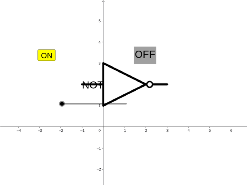
This example dynamically demonstrates the working principles of logic gates, visually showing the input-output relationships of basic logic operations (AND, OR, NOT). It involves core mathematical concepts like Boolean algebra, set operations, and truth tables. The construction uses GeoGebra commands/objects such as Segment, Point, Semicircle, and CircumcircleArc. Suitable for high school students and learners interested in computer science fundamentals.
GeoGebra Commands & Parameters
Segment(A, B) → fSegment(C, B) → gSegment(A, C) → hPoint(f) → DSegment(D, E) → iSegment(C, F) → jSegment(G, H) → kSegment(H, I) → lSegment(G, J) → mSemicircle(J, I) → cPoint(k) → LSegment(K, L) → pPoint(k) → NSegment(M, N) → qPoint(c) → OSegment(O, P) → rCircumcircleArc((-0.5, 3), (1.5, 2.5), O) → eCircumcircleArc((-0.5, 1), (1.5, 1.5), O) → sCircumcircleArc((-0.5, 3), (0.2, 2), (-0.5, 1)) → dCircumcircleArc((0, 3), (1.5, 2.5), O) → tCircumcircleArc((0, 1), (1.5, 1.5), O) → c_1CircumcircleArc((0, 3), (0.5, 2), (0, 1)) → d_1
AI Drawing Prompt Reference
Draw a dynamic illustration showing how logic gates work, visually representing the input-output relationships of AND, OR, and NOT operations. Include three input points connected by segments forming three distinct geometric structures, with semicircles and arcs indicating outputs. Use sliders to control input states, changing the output shapes based on Boolean algebra rules to demonstrate truth tables and set operations.
The prompt above was compiled from the original drawing commands and is for reference only.