
Logic Circuits: Geometric Visualization of Logic Gates
Loading the math board and drawing, please wait…
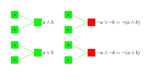
① This GeoGebra example constructs a visual logic circuit using geometric primitives—points, polygons, midpoints, and segments—to represent logic gates and signal flow. ② Core mathematical concepts include Boolean algebra, piecewise functions for gate behavior, matrices for state transitions, and planes/tangent lines to model threshold conditions. ③ Construction details: The summary lists commands like Point, Polygon, Midpoint, Segment, and objects such as B, a, I, J, K, L, q3, i, j, k, l, b, q4, plus many named polygons (poly3, poly8) and segments (r_1, s_1), indicating a multi-layer geometric network. ④ This is ideal for high school or undergraduate students learning discrete mathematics, digital logic design, or geometric modeling, and for educators demonstrating how abstract logical operations can be mapped to spatial configurations.
GeoGebra Commands & Parameters
Point(yAxis) → BPoint(xAxis) → IPoint(xAxis) → JPolygon(I, J, K, L) → q3, i, j, k, lPolygon(I, J, K, L) → q4, i_1, j_1, k_1, l_1Midpoint(I, L) → MPolygon(V, W, 4) → poly3, r_1, s_1, t_1, d_1, Z, A_1Polygon(R_1, S_1, 4) → poly8, b_2, c_2, d_2, e_2, T_1, U_1Polygon(V_1, W_1, 4) → poly9, f_3, g_3, h_3, i_3, Z_1, A_2Polygon(R_1, S_1, T_1, U_1) → q5, j_3, k_3, l_3, u_1Polygon(V_1, W_1, Z_1, A_2) → q6, v_1, w_1, z_1, m_3Polygon(V, W, Z, A_1) → q7, v, w, z_2, n_3Midpoint(A_1, V) → B_2Midpoint(A_2, V_1) → C_2Midpoint(U_1, R_1) → D_2Segment(T_2, B_2) → p_3Segment(P, B_2) → q_3Segment(E, M) → mSegment(C, M) → nSegment(G, D_2) → r_3Segment(H, D_2) → s_3Segment(N, C_2) → t_3Segment(O, C_2) → a_3
AI Drawing Prompt Reference
Create a geometric visualization of a logic circuit. Place two points on the coordinate axes as inputs. Draw two quadrilaterals to represent logic gates, each defined by four vertices. Take midpoints on one side of these quadrilaterals)Skip, and construct several regular quadrilaterals as additional gates, connected by edges to the midpoints. From these midpoints, draw multiple segments to other points or midpoints, forming signal flow paths. The overall composition is a multi-layer geometric network of polygons, midpoints, and segments, modeling logic gate behavior and state transitions.
The prompt above was compiled from the original drawing commands and is for reference only.