
Thin Slicing Geometry Proofs 2: Parallelograms and Function-Based Relations
Loading the math board and drawing, please wait…
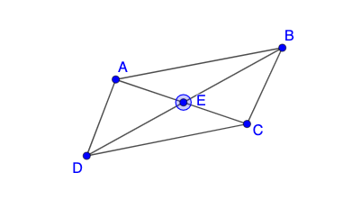
This GeoGebra example demonstrates a “thin slicing” geometry proof strategy by turning geometric configurations into checkable functional relationships. It centers on properties of parallelograms and general quadrilateral geometry in the plane, together with function-driven expressions (including power/fraction-like behavior) that encode how constructed elements correspond. The construction relies on building key segments and rays, selecting critical points, and then using mirror transformations to create symmetric counterparts (e.g., primed points) that enable stepwise verification of the proof idea. Concretely, it uses the commands Segment, Point, Ray, and Mirror, along with multiple geometric objects (such as points like D, B, E, A and their mirrored/primed versions like E', C') and several function objects (e.g., f, g, g', plus additional related expressions) to form a sequence of thin-slice arguments in a unified diagram. Designed for upper-secondary learners through early university study, it is well suited for classroom demonstration and practice in geometry proof visualization and function-assisted reasoning.
GeoGebra Commands & Parameters
Segment(D, B) → fPoint(f) → ERay(E, A) → gMirror(E, E) → E'Mirror(A, E) → C'Ray(E', C') → g'Point(g') → CSegment(E, A) → hSegment(E, C) → iSegment(D, A) → jSegment(C, B) → kSegment(A, B) → lSegment(D, C) → m
AI Drawing Prompt Reference
Construct a planar geometry figure aimed at a thin-slicing proof for parallelograms and general quadrilaterals. Start with two points D and B and draw the segment DB as the primary given connection. Use the relation associated with that segment to define a point E, then draw the ray from E toward A (direction g). Create a symmetric counterpart E′ by mirroring E with respect to E, and obtain C′ by mirroring A with respect to E. From E′ draw the ray through C′ (direction g′), which determines the corresponding point C. Finally, add the verification segments EA, EC, DA, CB, AB, and DC so that the diagram contains D, B, E, A, and the primed symmetric points E′ and C′, together with their connecting lines for stepwise functional/relational checking.
The prompt above was compiled from the original drawing commands and is for reference only.