
Illusion straight line check
Loading the math board and drawing, please wait…
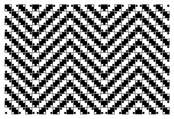
This example demonstrates how to verify the straight lines in an optical illusion. The key mathematical concepts include lines, geometric construction, and coordinate geometry. The construction involves using the OrthogonalLine command and objects such as A, B, C, D, E, F, G, H, I, a, b, c, d, e, f, g, h, o, text1, text2. It is suitable for middle or high school mathematics teaching to understand geometric principles and graphical verification.
GeoGebra Commands & Parameters
OrthogonalLine(C, xAxis) → aOrthogonalLine(D, xAxis) → bOrthogonalLine(E, xAxis) → cOrthogonalLine(F, xAxis) → dOrthogonalLine(G, xAxis) → eOrthogonalLine(H, xAxis) → fOrthogonalLine(I, xAxis) → gOrthogonalLine(J, xAxis) → h
AI Drawing Prompt Reference
Create an optical illusion diagram to verify straight lines. On a coordinate plane, draw several vertical lines from distinct points at various heights and horizontal positions down to the horizontal axis, forming a set of perpendicular reference lines. Include a clear horizontal baseline and mark the starting points of these vertical lines. The arrangement should create a visual effect that makes the lines appear slanted or curved, even though they are geometrically straight. This diagram is intended for middle or high school math demonstration, focusing on geometric construction and coordinate geometry.
The prompt above was compiled from the original drawing commands and is for reference only.