
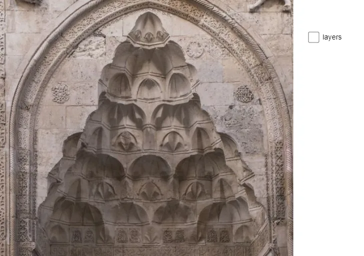
Geometry construction themed on Sivas Şifaiye Madrassa
Loading the math board and drawing, please wait…
In collections
Fatin Uluengin - muqarnas
This GeoGebra example demonstrates a systematic plane-geometry construction—using many key points and connected polyline/segment structures—to build a visually guided mathematical diagram inspired by the Şifaiye Madrassa theme. The core ideas include geometric construction (defining and connecting points), circle-related geometric relations, and a possible integration of conic-curve concepts through constrained geometry and the resulting shapes. Construction-wise, it is driven by GeoGebra commands Point, PolyLine, and Segment, with numerous point objects (e.g., A, B, C… and indexed variants like A_1, B_1, C_1…) serving as the backbone of the configuration; segments and polylines then form outlines, auxiliary constraints, and the structure that supports the depicted geometry. Suitable for high school to early university students, for lessons on geometric construction, intuitive circle/conic understanding, and hands-on exploration in interactive geometry.
GeoGebra Commands & Parameters
Point(yAxis) → MPolyLine(T, S, J, I, H, R, Q, P, O, N, M, L, K) → fSegment(U, V) → gSegment(G, F) → hPolyLine(M_1, L_1, C_1, B_1, A_1, Z, W, K_1, J_1, I_1, H_1, G_1, F_1, E_1, D_1) → iSegment(E, D) → jPolyLine(P_1, Q_1, V_1, U_1, T_1, S_1, R_1, F_2, E_2, D_2, C_2, B_2, A_2, Z_1, W_1) → kSegment(N_1, O_1) → lSegment(I_2, G_2) → mPolyLine(U_2, T_2, K_2, J_2, C, H_2, S_2, R_2, Q_2, P_2, O_2, N_2, M_2, L_2) → nPoint(yAxis) → D_3PolyLine(V_2, W_2, A_3, Z_2, I_3, H_3, G_3, F_3, E_3, D_3, C_3, B_3) → pPolyLine(J_3, K_3, T_3, U_3, L_3, M_3, N_3, O_3, P_3, Q_3, R_3, S_3) → qPolyLine(V_3, W_3, Z_3, A_4, B_4, C_4, D_4) → rPolyLine(E_4, F_4, H_4, G_4, K_4, J_4, I_4) → s
AI Drawing Prompt Reference
On a coordinate plane, start by setting a vertical reference line and place several key points along it, then use those points to build multiple connected polylines that form upper, lower, and side boundary contours. Next, connect corresponding pairs of the polyline points with straight segments to act as the main structural edges and auxiliary braces, linking endpoints to preserve a coherent, roughly symmetric layout. Finally, use the remaining grouped points to draw additional long polylines that tie the outer contours with inner structure, producing a construction-style diagram built from point, segment, and polyline relationships, with an overall arrangement inspired by circle-related geometry.
The prompt above was compiled from the original drawing commands and is for reference only.