
Geometric Construction of Measurement Error
Loading the math board and drawing, please wait…
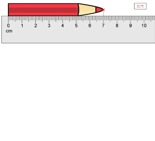
This example demonstrates the geometric construction of measurement error. Key mathematical concepts include geometric construction and error analysis. It uses commands like Polygon, Sequence, Segment, and Point in GeoGebra. Suitable for high school mathematics education, particularly in geometry and error analysis courses.
GeoGebra Commands & Parameters
SelectedElement(list3) → precisionPolygon(A, A - (0.5, 0), A - (0.5, 2), A + (15.5, -2), A + (15.5, 0)) → poly1, a, b, c, d, eSequence(Segment[A + (i, 0), A + (i, -0.5)], i, 0, 15) → list1Segment(A - (0.5, 0), A + (15.5, 0)) → fSequence(Segment[A + (i - 0.5, 0), A + (i - 0.5, -0.4)], i, 1, 15) → list5Point(Segment[B + (5.05, 0.5), B + (15, 0.5)]) → CSequence(Sequence[Segment[A + ((0.5 * i) + (0.1 * j), 0), A + ((0.5 * i) + (0.1 * j), -0.3)], j, 1, 4], i, 0, 29) → list6Segment(B, Intersect[OrthogonalLine[B, f], f]) → mSegment(C, Intersect[OrthogonalLine[C, f], f]) → nSegment(B + (0.06, 0.06), B + (0.06, 0.95)) → gSegment(B + (0.05, 0.05), B + (0.05, 0.98)) → Segment[B + (0.05, 0.05), B + (0, 0.95)]Segment(B + (0, 0.03), B + (0, 0.94)) → iSequence(Sequence[Segment[A + (i + (0.2 * j), 0), A + (i + (0.2 * j), -0.3)], j, 1, 4], i, 0, 14) → list2Corner(1, 1) → C_1Corner(1, 2) → C_2Corner(1, 3) → C_3Corner(1, 4) → C_4Corner(1, 5) → C_5Polygon({(measured + precision / 2, -0.07), (measured + precision / 2, 0.07), (measured - precision / 2, 0.07), (measured - precision / 2, -0.07)}) → poly2Segment((measured - precision / 2, -0.1), (measured - precision / 2, 0.1)) → jSegment((measured + precision / 2, -0.1), (measured + precision / 2, 0.1)) → l
AI Drawing Prompt Reference
Draw a geometric representation of measurement error with a square of side length 16, with its bottom-left corner at point A. Draw a horizontal line segment f in the middle of the square's bottom edge. Draw 16 equally spaced vertical line segments of length 0.5 along the bottom edge of the square. Draw a vertical line segment m from point B, perpendicular to line segment f. Draw a vertical line segment n from point C, perpendicular to line segment f. Draw a line segment g from point B with a length of 0.95. Draw a line segment i from point B with a length of 0.94. Draw 15 equally spaced vertical line segments of length 0.3 along the right edge of the square. Draw a rectangle to represent the measurement error, with a width of half the measured value plus or minus precision and a height of 0.1.
The prompt above was compiled from the original drawing commands and is for reference only.