
Geometric Construction for a Normal Form (Line–Angle Relationships)
Loading the math board and drawing, please wait…
In collections
COORDINATE GEOMETRY
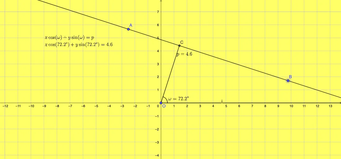
This example illustrates the “Normal Form” idea by converting algebra/trigonometric relationships into an explicit geometric configuration. Students can visualize how equivalent constraints manifest as intersections, orthogonality, and measurable angles, making the underlying structure easier to reason about. Key concepts include geometric line/segment/ray objects, angle measurement, line intersection, perpendicular (orthogonal) construction, and linking quadratic or trigonometric forms to concrete geometric elements (useful when discussing parallel/quadrilateral and even solid-geometry contexts via projection or decomposition). Construction details (from the provided GeoGebra commands) rely on: Line, OrthogonalLine, Intersect, Segment, Point, Ray, Angle, and If (for conditional labeling or branch-based display). The model centers on points such as A, B, C, D, E, F, and O, together with angles α and β and auxiliary objects (e.g., rays/lines and text labels text1–text3) to highlight the key angle relations produced by the orthogonal and intersecting lines. Suitable for upper-secondary through early college learners, especially for lessons and explorations in trigonometry, geometric construction, and interpreting quadratic relationships geometrically.
GeoGebra Commands & Parameters
Line(A, B) → fOrthogonalLine(O, f) → gIntersect(f, g) → CSegment(O, C) → hPoint(xAxis) → DRay(O, D) → iAngle(D, O, C) → αIf(α < π, Angle[D, O, C], (-Angle[C, O, D])) → βPoint(h) → FIf(α < π, CircleArc[O, E, F], CircleArc[O, F, E]) → c
AI Drawing Prompt Reference
Draw a horizontal line and place a fixed point above it. Construct a perpendicular from this point to the line, marking the foot of the perpendicular. Connect the fixed point to the foot to form a segment. Choose another point on the horizontal axis, then draw a ray from the fixed point through this new point. Measure the angle between the ray and the perpendicular segment)Skip. Based on the angle size, draw an arc centered at the fixed point, connecting the foot and a point on the ray. Finally, place a point on the perpendicular segment to help illustrate the angle relationships.
The prompt above was compiled from the original drawing commands and is for reference only.