
Fixing 3D Objects on the Screen with Dynamic Coloring: Sliders and Buttons
Loading the math board and drawing, please wait…
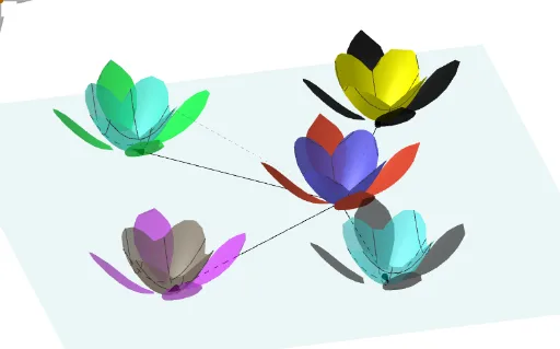
This example demonstrates how to keep an object visually fixed in a 3D GeoGebra view while using sliders and buttons to drive parameter changes, producing dynamic updates such as color/display variation. The main mathematical ideas are 3D geometric construction, vector-based positioning, translation transformations (Translate), and parameterization along a path (PathParameter). Construction highlights: Vector, CornerThreeD, Segment, and Point are used to define the key 3D elements (points, edges, and corner references). PathParameter provides a parameter tied to a path for selecting/locating dependent points. Translate then moves or repositions structures consistently in 3D space as parameters change. Numerous objects (e.g., coordinate/size and color components like MMx, MMdim, MMv, MMy, MMcentro, O, v, and the color channels sr/sg/sb with pr/pg/pb, etc.) reflect the strategy of decomposing geometry and visual attributes into computable variables so that the interaction controls update the resulting visualization. Suitable for upper secondary to pre-university learners and for teaching dynamic geometry: parameter-driven 3D transformations plus visualization via linked coloring.
GeoGebra Commands & Parameters
Vector(CornerThreeD[-1, 12]) → MMxCornerThreeD(-1, 9) → MMdimVector(O, O + (50 * MMy)) → vVector(O, O + (50 * MMx)) → hSegment(O + h + (0.5 * v), O + (3 * h) + (0.5 * v)) → srSegment(O + h + v, O + (3 * h) + v) → sgSegment(O + h + (1.5 * v), O + (3 * h) + (1.5 * v)) → sbSegment(O + h + (2 * v), O + (3 * h) + (2 * v)) → soPoint(sr) → PrPoint(sg) → PgPoint(sb) → PbPoint(so) → PoPathParameter(Pr) → prPathParameter(Pg) → pgPathParameter(Pb) → pbPathParameter(Po) → poVector(A, B) → uVector(A, C) → wVector(A, D) → bVector(A, E) → dTranslate(B1, u) → B3Translate(B1, w) → B5Translate(B1, b) → B7Translate(B1, d) → B9Translate(B2, u) → B4Translate(B2, w) → B6Translate(B2, b) → B8Translate(B2, d) → B10
AI Drawing Prompt Reference
Create a 3D scene with a vector-based construction anchored at a base point O. Build a main dimension reference from a corner, then define two direction vectors v and h from O using fixed scale factors. From O plus appropriate combinations of h and v, construct four segment edges (sr, sg, sb, so). Choose corresponding points Pr, Pg, Pb, Po on these segments and tie each to a parameter (pr, pg, pb, po) that varies along its path. From a starting point A, define four direction vectors u, w, b, d. Finally, translate the same base structure along each of u, w, b, d to form two mirrored/update-linked sets of points (B3/B5/B7/B9 and B4/B6/B8/B10), so the parameterized points drive the resulting dynamic visual/color components.
The prompt above was compiled from the original drawing commands and is for reference only.