
Dynamic Rhombus: rotate and mirror to control shape and angles
Loading the math board and drawing, please wait…
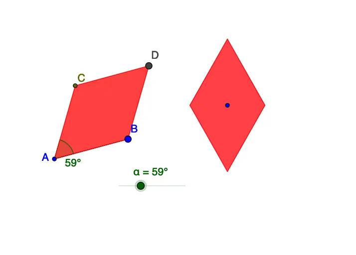
This example demonstrates how to build a dynamic, adjustable rhombus in GeoGebra, where the figure can be repositioned and reshaped using geometric transformations while preserving rhombus properties. Key concepts include rhombus symmetry, angle constraints (Angle, including parameters such as α and β), and distance/length conditions (Distance). Algebraic relationships (and related numeric constraints) help maintain the required geometric structure, while cosine/angle relationships support interpreting or controlling directional/angle measures. The construction relies on the provided GeoGebra commands and objects: Segment and Circle for establishing sides and auxiliary loci; Rotate and Mirror to generate and update symmetric/rotated points (e.g., A/B/C and derived points such as a′/c′, F′/G′); Polygon to display the rhombus as poly1 and poly2; Distance to measure quantities like distanceAD and distanceBC, together with TextAD/TextBC for labeling; and Angle to compute and show angle values such as β and α. Suitable for middle-school geometry lessons, dynamic geometry demonstrations, and student activities on parameterized geometric construction and transformation-based reasoning.
GeoGebra Commands & Parameters
Segment(A, B) → aCircle(A, B) → cRotate(B, α, A) → CSegment(C, B) → bMirror(A, b) → DPolygon(A, B, D, C) → poly1, a_1, b_1, a', c_1Distance(A, D) → distanceADDistance(B, C) → distanceBCMirror(G, E) → G'Mirror(F, E) → F'Polygon(F', G, F, G') → poly2, f', g, f, g'Angle(B, A, C) → β
AI Drawing Prompt Reference
Create a dynamic rhombus-style figure on the plane. Start with two points to define a side, then use a circle relationship to determine auxiliary loci and construct a third point by rotating around one endpoint with a controlled angle. Connect the second and third points to form the next side, then obtain the opposite vertex by mirroring the original endpoint across the appropriate auxiliary line, and finally form the main quadrilateral by connecting the four key points as a polygon. Show key measures by marking distances between a vertex and its mirrored counterpart and between the other pair of corresponding vertices. Construct a second polygonal region using additional pairs of mirrored points related to the first figure, and compute and display the angle β formed by the two rhombus sides at the specified vertex.
The prompt above was compiled from the original drawing commands and is for reference only.