
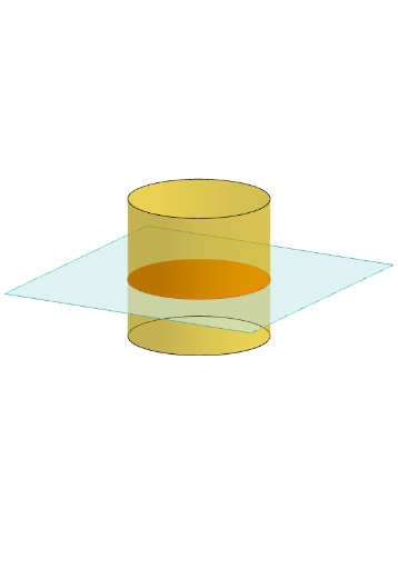
Cylinder Cross-Section
Loading the math board and drawing, please wait…
This example demonstrates how to dynamically interact with and visualize the cross-sections of a cylinder. Key math concepts include solid geometry, intersection lines between planes and solids, and geometric transformations. Construction highlights from the summary involve commands like Polygon, PointIn, Translate, Rotate, Cylinder, Plane, IntersectPath, OrthogonalLine, and Ends. Suitable for high school geometry education to intuitively understand the relationship between cross-sectional shapes and parameter variations.
GeoGebra Commands & Parameters
Polygon(B + (-2, -2), B + (2, -2), B + (2, 2), B + (-2, 2)) → poly3, e, f, g, iPointIn(poly3) → CTranslate((0, 0, 0), Vector[B, C]) → APolygon(A + (-4, -4), A + (4, -4), A + (4, 4), A + (-4, 4)) → poly1, a, b, c, dRotate(Rotate[Translate[poly1, Vector[A, A + (0, 0, h)]], (90° * s), A + (0, 0, h), yAxis], (90° * t), A, zAxis) → poly2Rotate(D, 120°, (0, 0, 0)) → EPolygon(D, E, 3, xOyPlane) → poly4, j, k, l, FCylinder((0, 0, 0), (0, 0, 4), 2) → m, e_1, f_1, oPointIn(poly2) → GPointIn(poly2) → HPointIn(poly2) → IPlane(G, I, H) → nIntersectPath(n, m) → poly6OrthogonalLine(A, n) → d_1Ends(m) → g_1, g_1_1
AI Drawing Prompt Reference
Draw a cylinder with radius 2 and height 4, centered at the origin with its axis along the vertical direction. Inside the cylinder, construct an inclined plane determined by three random points on the cylinder's lateral surface, and show the intersection curve between this plane and the cylinder as a closed cross-section path. Above the cylinder, place a rectangular plane that can rotate about both vertical and horizontal axes, and select three points on it to define another cutting plane. Additionally, draw an equilateral triangle in the base plane and show its rotated position. Display the cylinder, cross-section curves, rotating planes, and auxiliary geometric elements in a 3D view.
The prompt above was compiled from the original drawing commands and is for reference only.