
Cylinder Anamorphosis (Anamorphic Projection on a Cylinder)
Loading the math board and drawing, please wait…
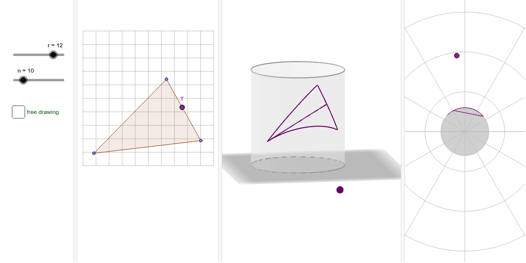
This example demonstrates how to project a plane drawing onto a cylinder surface, creating an anamorphic or distorted image. The core mathematical concepts involve 3D projection transformations, parameterization of cylindrical surfaces, and geometric correspondences between planes and curved surfaces. Construction highlights include using GeoGebra commands such as OrthogonalPlane, PointIn, Line, Ray, Circle, Cylinder, Mirror, Translate, Rotate, Locus, and LocusEquation to build the cylinder, project points, and trace their paths. The example is suitable for high school or university courses in solid geometry, analytic geometry, or computer graphics, helping students intuitively understand the mathematical principles behind non-planar projections and geometric constructions.
GeoGebra Commands & Parameters
OrthogonalPlane(O, xAxis) → wPointIn(w) → HLine(A, xAxis) → fPoint(f) → CRay(A, C) → gPoint(g) → BIf(abs(x(B_f) - x(B)) ≤ abs(x(B_c) - x(B)), B_f, B_c) → B'Sequence(Segment[(x(A) + i, y(A)), (x(A) + i, y(A) + x(B') - x(A))], i, 0, x(B') - x(A), 1) → list1Circle((0, 0), r) → cSequence(Segment[(x(A), y(A) + i), (x(B'), y(A) + i)], i, 0, x(B') - x(A), 1) → list2Mirror(list1, c) → list1'Mirror(list2, c) → list2'Cylinder(c, 24.735270934851805) → a, d, bPoint(list1) → F_2Polygon(D, E, F_2) → poly1, f_1, d_1, ePoint(poly1) → GMirror(G, c) → G'LocusEquation(G', G) → iLocus(G', G) → loc1Point(d) → IPoint(d) → JPoint(d) → KLineBisector(I, J, d) → jLineBisector(J, K, d) → lIntersect(j, l) → LIntersect(c, xAxis) → M, NPoint(list1) → PVector(P, L) → uTranslate(M, u) → M'Translate(N, u) → N'Polygon(M, N, N', M') → poly2, m, n_1, n', m'Sequence(Segment[(x(M) + i, 0, z(M)), (x(M) + i, 0, z(M) + m')], i, 0, m, m / n) → list3Sequence(Segment[(x(M), 0, z(M) + i), (x(N), 0, z(N) + i)], i, 0, m', m' / n) → list4Plane(M', N', N) → hPointIn(poly2) → QPointIn(poly2) → RPointIn(poly2) → SPolygon(Q, S, R) → poly3, r_1, q, sPoint(poly3) → TSegment(H, T) → pOrthogonalLine(H, xOyPlane) → tIntersect(t, xOyPlane) → UPlane(U, T, H) → oIntersectPath(o, a) → c_1Corner(c_1) → V, W, Z, A_1OrthogonalLine(T, t, o) → g_1Mirror(H, g_1) → H'Mirror(T, g_1) → T'Segment(H', T') → p'Line(T, H') → h_1Intersect(p, c_1) → C_1, D_1Plane(O, xOyPlane) → vLine(D_1, g_1) → i_1Line(D_1, h_1) → j_1Intersect(j_1, xOyPlane) → B_1PointIn(w) → E_1Locus(D_1, T) → loc3Locus(B_1, T) → loc4Circle(O, M, v) → e_1PointIn(h) → FLine(H, zAxis) → k_1Intersect(k_1, v) → G_1Plane(G_1, F, H) → a_1OrthogonalLine(F, k_1, a_1) → l_1IntersectPath(a_1, a) → p_1Corner(p_1) → H_1, I_1, J_1, K_1Line(F, H) → m_1Intersect(m_1, p_1) → L_1, M_1Line(L_1, l_1) → q_1Mirror(m_1, q_1) → s_1Intersect(s_1, v) → N_1