
Cutting a Pyramid with an Interactive Plane
Loading the math board and drawing, please wait…
In collections
Cutting solids by a plane
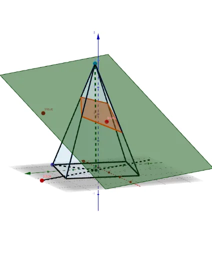
This example demonstrates how an interactive draggable plane cuts a pyramid (constructed from cube vertices), showing in real time the resulting cross-section polygon and the volume of the remaining part. Core mathematical concepts include solid geometry intersections between planes and polyhedra, cross-section shapes (quadrilaterals), volume calculation, and geometric transformations (translation, reflection, scaling) as well as exponent relationships. Construction highlights: using GeoGebra commands such as Point, Cube, Midpoint, Line, Circle, Mirror, Plane, Center, OrthogonalLine, Vector, Translate, Segment, Intersect, Polygon, Sequence, Pyramid, and IntersectPath, the cube and its faces are built first, then a cutting plane is defined via points, lines, and planes, with IntersectPath generating the cross-section and volumes updating dynamically. Suitable for high school or early college students to explore spatial geometry properties of plane sections of polyhedra, and for teachers to demonstrate interactive geometric inquiry in class.
GeoGebra Commands & Parameters
Point(Circle[B, Distance[A, B], Segment[A, B]]) → CCube(A, B, C) → a, D, faceCDHG, faceEFGH, arêteAD, arêteAB, arêteBC, arêteCD, arêteAE, arêteDH, arêteEH, arêteEF, E, arêteBF, arêteFG, arêteCG, arêteGH, F, G, H, faceABCD, faceADHE, faceABFE, faceBCGFMidpoint(C, A) → IMidpoint(F, H) → JLine(J, I) → fCircle(I, Distance[A, B], f) → cPoint(c) → KMidpoint(F, C) → MMirror(K, I) → K'Line(K', K) → gCircle(I, (1.2 * Distance[A, B]), g) → dPoint(d) → LPlane(L, K, K') → pCircle(K', L, K) → eCenter(e) → NOrthogonalLine(N, p) → hPoint(h) → OVector(I, O) → uTranslate(p, u) → p'Segment(K', K) → bLine(L, b) → f_1Point(arêteEF) → D_1OrthogonalLine(K, p) → h_1Plane(K', h_1) → p_1OrthogonalLine(K, p_1) → k_1Line(K', k_1) → l_1Intersect(f_1, l_1) → E_1Intersect(k_1, f_1) → F_1Mirror(F_1, K) → G_1Mirror(E_1, K') → H_1Polygon(F_1, E_1, H_1, G_1) → q2, m_1, e_1, n_1, q_1Translate(q2, u) → q2'Circle(I, Distance[I, A], f) → qPoint(f) → SSegment(A, I) → iSegment(I, S) → jSequence(Rotate[A, i, f], i, 0, (2 * π), (2 * π / Sides)) → l1Polygon(l1) → poly1Sequence(Segment[Element[l1, i], S], i, 1, Length[l1]) → l3Pyramid(poly1, S) → k, face1, face10, face11, face12, face13, face14, face15, face16, face17, face18, face19, face3, face20, face21, face22, face23, face24, face25, face26, face27, face28, face29, face4, face30, face31, face32, face33, face34, face35, face36, face37, face38, face39, face5, face40, face41, arête1, arête2, arête3, arête4, arête5, arête6, arête7, arête8, face6, arête9, arête10, arête11, arête12, arête13, arête14, arête15, arête16, arête17, arête18, face7, arête19, arête20, arête21, arête22, arête23, arête24, arête25, arête26, arête27, arête28, face2, arête29, arête30, arête31, arête32, arête33, arête34, arête35, arête36, arête37, arête38, face8, arête39, arête40, arête41, face9IntersectPath(p', k) → poly2, P, I_1, J_1, K_1, L_1, M_1, N_1, O_1, Q_1, R_1, S_1, Q, T_1, U_1, V_1, W_1, Z_1, A_2, B_2, C_2, D_2, E_2, R, F_2, G_2, H_2, I_2, J_2, K_2, L_2, M_2, N_2, O_2, T, P_2, Q_2, l, m, n, r, s, t, g_1, d_1, Z, i_1, j_1, r_1, s_1, t_1, a_1, b_1, c_1, f_2, g_2, A_1, h_2, i_2, j_2, k_2, l_2, m_2, n_2, p_2, q_2, r_2, B_1, s_2, t_2, a_2, b_2, c_2, d_2, e_2, f_3, g_3, h_3, P_1, i_3, j_3, k_3, C_1
AI Drawing Prompt Reference
Create an interactive demonstration of a plane cutting through a pyramid constructed from cube vertices, showing the resulting cross-section polygon and the volume of the remaining part in real time. Build the cube first, then define the cutting plane by dragging points. Use path intersection to generate the cross-section and dynamically update the volume. Suitable for exploring spatial geometry properties and transformations.
The prompt above was compiled from the original drawing commands and is for reference only.