
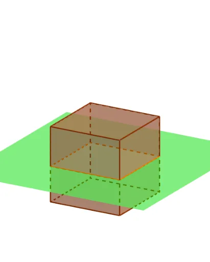
Cross Sections of a Cube by Steve Phelps (2)
Loading the math board and drawing, please wait…
In collections
intersection: surface-surface, curve-curve
intersection: surface-surface, curve-curve
intersection: surface-surface, curve-curve
intersection: surface-surface, curve-curve
This example demonstrates the various polygonal cross‑sections produced when a plane slices through a cube. It covers core concepts in solid geometry, planar sections of 3D solids, spatial transformations, and intersection curves. The construction employs GeoGebra commands such as Point, Cube, Translate, and IntersectPath, creating vertices (A, B, C…), faces (face1‑face4), edges (edge1‑edge5), parameters (shift, tilt, turn) and the resulting polygon (poly1). It is suitable for high‑school solid‑geometry lessons, geometric construction practice, and advanced GeoGebra animation demonstrations.
GeoGebra Commands & Parameters
Point(Circle[(2, -2, -2), Distance[(-2, -2, -2), (2, -2, -2)], Segment[(-2, -2, -2), (2, -2, -2)]]) → ACube((-2, -2, -2), (2, -2, -2), A) → a, B, faceABFE, faceCDEF, edge2, edge1, edge4, edgeAB, edge3, edgeBF, edgeCF, edgeCD, C, edge5, edgeDE, edgeAE, edgeEF, D, E, F, face1, face3, face2, face4Translate(Rotate[Rotate[Plane[(0, 1, 0), xAxis], tilt, xAxis], turn, zAxis], Vector[(0, 0, shift)]) → bIntersectPath(b, a) → poly1, G, i, j, k, H, I, J, K, L, f, g, h
AI Drawing Prompt Reference
Draw a cross-section of a cube. The cube consists of vertices, faces, and edges. A plane with parameters shift, tilt, and turn is translated and rotated, intersecting the cube to form a polygonal cross-section. The construction order is: first define a point, then create the cube, then apply translation and rotation, and finally compute the intersection of the plane with the cube to obtain the cross-section polygon.
The prompt above was compiled from the original drawing commands and is for reference only.