
Constructing Two Parallel Planes in 3D Geometry
Loading the math board and drawing, please wait…
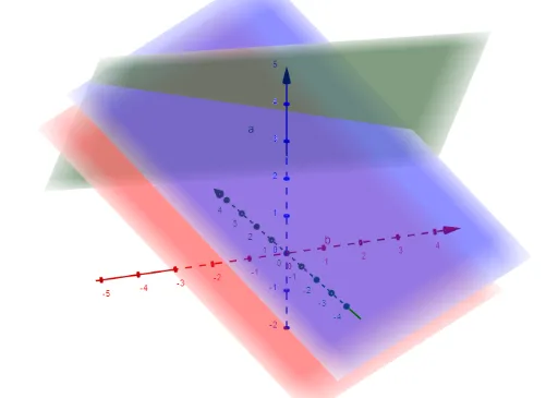
This example demonstrates how to construct and visualize two parallel planes in GeoGebra and examine the geometric outcomes produced by their spatial relationship (e.g., induced segments/sections under chosen constructions). The key mathematics concepts include solid geometry (properties of parallel planes), geometric construction with coordinate/vector reasoning (to define plane positions and orientations), and computation-oriented geometry logic using determinant-based tests and intersection computations. The construction leverages GeoGebra commands from the provided “construction summary”: Determinant (to derive/verify geometric constraints from coordinate relations or direction data) and IntersectPath (to compute intersection points along paths/sections). The involved objects M, d, c, b, a, f, g, h represent the key points/auxiliary elements used to define the planes and their associated sections/lines. It is suitable for advanced secondary school, early university prep, and teaching modules on 3D geometry, coordinate geometry, and visualization-driven math reasoning.
GeoGebra Commands & Parameters
Determinant(M) → dIntersectPath(a, b) → fIntersectPath(a, c) → gIntersectPath(b, c) → h
AI Drawing Prompt Reference
Draw two parallel planes in 3D space. Start by defining a plane using point M, then use vectors a, b, and c to define two planes. Next, compute the intersection line f between plane a and b, the intersection line g between plane a and c, and the intersection line h between plane b and c.
The prompt above was compiled from the original drawing commands and is for reference only.