
Connectivity Matrix by chris cambré (2)
Loading the math board and drawing, please wait…
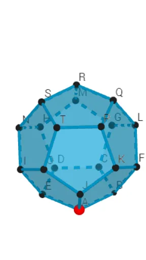
This example illustrates the concept of a connectivity matrix, involving core mathematical concepts of matrices and graph theory. Using GeoGebra commands such as Circle, Intersect, and Rotate, a visual model of a connectivity matrix is constructed. This example is suitable for high school mathematics education, particularly in matrix and graph theory courses.
GeoGebra Commands & Parameters
Circle(OO, 1, xOyPlane) → cIntersect(xAxis, c, 1) → ARotate(A, 60°) → BTableText({{"A", "B", "C", "D", "E", "F", "G", "H", "I", "J", "K", "L", "M", "N", "P", "Q", "R", "S", "T", "U"}}) → tekst2TableText({{"A"}, {"B"}, {"C"}, {"D"}, {"E"}, {"F"}, {"G"}, {"H"}, {"I"}, {"J"}, {"K"}, {"L"}, {"M"}, {"N"}, {"P"}, {"Q"}, {"R"}, {"S"}, {"T"}, {"U"}}) → tekst3Point(Circle[((A * (1 - sqrt(5))) + (B * (3 + sqrt(5)))) / 4, (Distance[A, B] * sqrt(10 + (2 * sqrt(5))) / 4), Segment[A, B]]) → CDodecahedron(A, B, C) → a, D, M, N, O, P, Q, R, S, T, zijvlakABCDE, zijvlakAEIOJ, E, zijvlakABFKJ, zijvlakBCGLF, zijvlakCDHMG, zijvlakDEINH, zijvlakINSTO, zijvlakJKPTO, zijvlakFKPQL, zijvlakGLQRM, zijvlakHMRSN, zijvlakPQRST, F, RibbeAE, RibbeAB, RibbeBC, RibbeCD, RibbeDE, RibbeAJ, RibbeEI, RibbeIO, RibbeJO, RibbeJK, G, RibbeFK, RibbeBF, RibbeFL, RibbeGL, RibbeCG, RibbeGM, RibbeHM, RibbeDH, RibbeHN, RibbeIN, H, RibbeNS, RibbeST, RibbeOT, RibbePT, RibbeKP, RibbePQ, RibbeLQ, RibbeQR, RibbeMR, RibbeRS, I, J, K, LJoin({{"A"}, Sequence[Element[MMM, 1, nn], nn, 1, 20]}) → RijAAJoin({{"B"}, Sequence[Element[MMM, 2, nn], nn, 1, 20]}) → RijBBJoin({{"C"}, Sequence[Element[MMM, 3, nn], nn, 1, 20]}) → RijCCJoin({{"D"}, Sequence[Element[MMM, 4, nn], nn, 1, 20]}) → RijDDJoin({{"E"}, Sequence[Element[MMM, 5, nn], nn, 1, 20]}) → RijEEJoin({{"F"}, Sequence[Element[MMM, 6, nn], nn, 1, 20]}) → RijFFJoin({{"G"}, Sequence[Element[MMM, 7, nn], nn, 1, 20]}) → RijGGJoin({{"H"}, Sequence[Element[MMM, 8, nn], nn, 1, 20]}) → RijHHJoin({{"I"}, Sequence[Element[MMM, 9, nn], nn, 1, 20]}) → RijIIJoin({{"J"}, Sequence[Element[MMM, 10, nn], nn, 1, 20]}) → RijJJJoin({{"K"}, Sequence[Element[MMM, 11, nn], nn, 1, 20]}) → RijKKJoin({{"L"}, Sequence[Element[MMM, 12, nn], nn, 1, 20]}) → RijLLJoin({{"M"}, Sequence[Element[MMM, 13, nn], nn, 1, 20]}) → RijMMJoin({{"N"}, Sequence[Element[MMM, 14, nn], nn, 1, 20]}) → RijNNJoin({{"O"}, Sequence[Element[MMM, 15, nn], nn, 1, 20]}) → RijOOJoin({{"P"}, Sequence[Element[MMM, 16, nn], nn, 1, 20]}) → RijPPJoin({{"Q"}, Sequence[Element[MMM, 17, nn], nn, 1, 20]}) → RijQQJoin({{"R"}, Sequence[Element[MMM, 18, nn], nn, 1, 20]}) → RijRRJoin({{"S"}, Sequence[Element[MMM, 19, nn], nn, 1, 20]}) → RijSSJoin({{"T"}, Sequence[Element[MMM, 20, nn], nn, 1, 20]}) → RijTTTableText({rij0, RijAA, RijBB, RijCC, RijDD, RijEE, RijFF, RijGG, RijHH, RijII, RijJJ, RijKK, RijLL, RijMM, RijNN, RijOO, RijPP, RijQQ, RijRR, RijSS, RijTT}, "c") → tekst5Point(ribben) → PP
AI Drawing Prompt Reference
Draw a regular dodecahedron with its vertices evenly distributed on a unit circle centered at the origin, starting from the intersection of the circle with the positive x-axis and rotating by 60 degrees each time to generate 20 vertices. Next to the dodecahedron, display a 20x20 connectivity matrix as a table, with rows and columns labeled by letters A through T, where the matrix entries indicate whether corresponding vertices are connected by an edge. Additionally, mark a point at the midpoint of each edge of the dodecahedron to highlight the edge structure. The overall composition should clearly show the three-dimensional shape of the dodecahedron and its correspondence with the matrix.
The prompt above was compiled from the original drawing commands and is for reference only.