
CIMAT Logo: Geometric Construction with Vectors, Transformations, and Functions
Loading the math board and drawing, please wait…
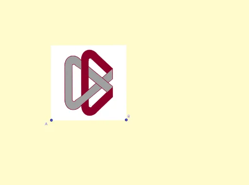
This GeoGebra example constructs a complex geometric logo named 'CIMAT', demonstrating how to combine vectors, perpendicular lines, midpoints, angle bisectors, reflections, translations, and various function curves (logarithmic and power functions) along with integral elements to create a mathematically aesthetic emblem. Core mathematical concepts include 2D vector operations, geometric transformations (reflection, translation, similarity), function graphs (logarithmic, power), and integral calculus ideas. Construction highlights: from the summary, commands such as Vector, OrthogonalLine, OrthogonalVector, Midpoint, Intersect, LineBisector, Mirror, Line, CurveCartesian, Segment, Polygon, Semicircle, and Translate are used, involving numerous objects (H, B, A, u, g, v, C, J, M, f, D, m, M', U, o, s, b, I, d, E, h, i, i', h', F, G, K, L, K', N, j, k, O, P, Q, P'). This example is suitable for high school and above, serving as an advanced exercise in geometric construction, transformations, and function integration, and as a reference for mathematical art design.
GeoGebra Commands & Parameters
Vector(A, B) → uOrthogonalLine(B, u, xOyPlane) → gOrthogonalVector(u) → vMidpoint(C, A) → JOrthogonalLine(C, v, xOyPlane) → fIntersect(g, f) → DLineBisector(A, B) → mMirror(M, m) → M'Intersect(f, m) → ULine(A, B) → sOrthogonalLine(A, s) → bLineBisector(A, C) → dIntersect(m, d) → EOrthogonalLine(I, b) → hOrthogonalLine(M, d) → iMirror(i, m) → i'Mirror(h, d) → h'Midpoint(E, M') → LMirror(K, L) → K'Intersect(m, h') → NOrthogonalLine(G, d) → jOrthogonalLine(F, d) → kIntersect(j, h') → OMirror(P, d) → P'Mirror(Q, d) → Q'CurveCartesian(((1 - t)^(3) * P) + (((3 * (1 - t)^(2)) * t) * S) + (((3 * (1 - t)) * t^(2)) * R) + (t^(3) * Q), t, 0, 1) → aMirror(a, d) → a'OrthogonalLine(P, g, xOyPlane) → lMirror(W, d) → W'Mirror(Z, d) → Z'Intersect(l, m) → VLine(Q, Z) → nLine(W, n) → pIntersect(g, h') → A_1Line(V, A_1) → qIntersect(q, p) → B_1OrthogonalLine(D_1, m) → eMirror(B_1, d) → C_1Mirror(V, d) → V'Segment(P', W) → tMirror(P', d) → P''Mirror(W, d) → W'_1Segment(P'', W'_1) → t'Mirror(Q', d) → Q''Mirror(Z', d) → Z''Segment(Q'', Z'') → h_1Segment(T, Z) → i_1Intersect(m, i_1) → F_1Intersect(p, i_1) → G_1Polygon(F_1, T, P, V) → q1, j_1, t_1, p_1, v_1Polygon(Q, B_1, G_1, Z) → q2, q_1, b_1, k_1, z_1Semicircle(V, B_1, xOyPlane) → cMirror(c, d) → c'Polygon(C_1, Q', Z', W') → q3, c_1, q', z', w'Intersect(t, m) → E_1Polygon(P', V', E_1) → t1, e_1, p', v'Line(Z', t') → rIntersect(r, j) → H_1Intersect(r, w') → I_1Intersect(t', m) → J_1Intersect(r, m) → K_1Polygon(Z, W, P', T) → q4, z_2, w, f_1, t_2Polygon(I_1, W', J_1, K_1) → q5, g_1, l_1, m_1, n_1Vector(Q', P') → u_1Translate(a', u_1) → a''Mirror(a'', d) → a'''Translate(c', u_1) → c''Mirror(c'', d) → c'''Translate(P', u_1) → P''_1Translate(V', u_1) → V''Translate(C_1, u_1) → L_1Mirror(P''_1, d) → M_1Mirror(V'', d) → V'''Mirror(L_1, d) → N_1Polygon(M_1, V''', V'', P''_1) → q6, r_1, v''', v'', p''_1Polygon(T, L_1, P') → t2, s_1, t_3, a_1Mirror(t2, d) → t2'Mirror(T, d) → T'Mirror(L_1, d) → O_1Segment(T', O_1) → d_1Polygon(P, Q, B_1, V) → q7, p_2, q_2, f_2, v_2Polygon(M_1, P, N_1, V''') → q8, g_2, p_3, h_2, i_2Polygon(V'', L_1, P', P''_1) → q9, j_2, k_2, l_2, m_2Polygon(P', Q', C_1, V') → q10, n_2, r_2, s_2, a_2Semicircle(V, B_1, xOyPlane) → c_2Mirror(c, d) → c'_1Translate(c', u_1) → c''_1Mirror(c'', d) → c'''_1Translate(a', u_1) → a''_1Mirror(a''_1, d) → o_1Polygon(A, B, D, C) → q11, a_3, b_2, d_2, c_3
AI Drawing Prompt Reference
Draw a mathematical logo named CIMAT. Start with two points defining a vector, then construct a perpendicular line through one endpoint and another perpendicular vector. Find midpoints and angle bisectors, and use intersections to locate key points. Reflect several points across lines and midpoints to create symmetry. Use cubic Bezier curves to connect specific points, then mirror those curves. Add more perpendicular and parallel lines, find intersections, and connect them with segments. Finally, connect symmetric points with segments to complete the emblem. The design incorporates vectors, perpendiculars, midpoints, angle bisectors, reflections, translations, Bezier curves, and line segments, forming an artistic geometric pattern.
The prompt above was compiled from the original drawing commands and is for reference only.