
Building Models with Cubes
Loading the math board and drawing, please wait…
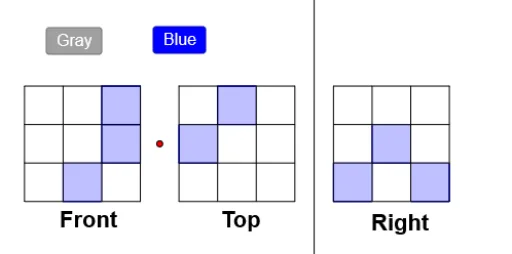
This example demonstrates how to construct various models using cubes. It involves core mathematical concepts such as random variables, matrices, and similarity transformations. Using GeoGebra commands like AttachCopyToView, Polygon, Intersect, Segment, and Point, complex geometric shapes can be constructed. Suitable for middle school students and teachers.
GeoGebra Commands & Parameters
AttachCopyToView(PolyLine[(4.64,0.74), (4.64,0.84), (4.64,0.92), (4.64,1.02), (4.64,1.14), (4.64,1.3), (4.64,1.38), (4.64,1.46), (4.66,1.54), (4.66,1.62), (4.68,1.68), (4.74,1.72), (4.82,1.66), (4.82,1.5), (4.82,1.4), (4.82,1.28), (4.82,1.2), (4.84,1.1), (4.86,1.04), (4.86,0.94), (4.86,0.84), (4.86,0.74), (4.86,0.64), (4.92,0.74), (4.92,0.82), (4.92,0.9), (4.92,1), (4.92,1.14), (4.92,1.22), (4.92,1.32), (4.92,1.4), (4.92,1.5), (4.94,1.56), (5,1.52), (5.02,1.44), (5.06,1.34), (5.08,1.26), (5.08,1.18), (5.1,1.12), (5.1,1.04), (5.1,0.94), (5.12,0.86), (5.14,0.76), (5.14,0.68), (5.16,0.62), (5.18,0.68), (5.18,0.76), (5.18,0.84), (5.18,0.94), (5.2,1.04), (5.22,1.12), (5.24,1.18), (5.26,1.26), (5.26,1.34), (5.26,1.44), (5.26,1.52), (5.26,1.6), (5.3,1.54), (5.32,1.48), (5.36,1.38), (5.38,1.3), (5.4,1.22), (5.42,1.16), (5.44,1.1), (5.46,1.04), (5.48,0.96), (5.5,0.9), (5.52,0.84), (5.52,0.74), (5.54,0.86), (5.54,0.98), (5.54,1.12), (5.54,1.2), (5.52,1.3), (5.52,1.38), (5.52,1.48), (5.52,1.4), (5.6,1.32), (5.64,1.26), (5.7,1.18), (5.72,1.1), (5.74,1.02), (5.76,0.96), (5.78,0.9), (5.8,0.82), (5.8,0.74), (NaN,NaN), true], 1, (-4.300000000000001, -2.6600000000000015), (6.5000000000000036, 6.3), (0, 448), (540, 0)) → stroke1Polygon(A, B, 4) → poly1, f, g, h, k, C, DPolygon(B, E, 4) → poly2, p, q, r, s, J, KPolygon(E, L, 4) → poly3, t, a, b, c, M, NPolygon(D, C, 4) → poly4, d, e, i_1, j_1, O, PPolygon(C, J, 4) → poly5, k_1, l_1, m_1, n_1, Q, RPolygon(J, M, 4) → poly6, p_1, q_1, r_1, s_1, S, TPolygon(P, O, 4) → poly7, t_1, a_1, b_1, c_1, U, VPolygon(O, Q, 4) → poly8, d_1, e_1, f_2, g_2, W, ZPolygon(Q, S, 4) → poly9, h_2, i_2, j_2, k_2, A_1, B_1Intersect(f, k) → C_1Segment(C_1, D_1) → l_2Intersect(i_2, j_2) → E_1Segment(D_1, E_1) → m_2Intersect(b_1, c_1) → F_1Segment(E_1, F_1) → n_2Segment(F_1, C_1) → p_2Intersect(f, g) → G_1Intersect(a_1, b_1) → H_1Segment(G_1, H_1) → q_2Intersect(e_1, f_2) → I_1Intersect(p, q) → J_1Segment(I_1, J_1) → r_2Intersect(h, k) → K_1Intersect(a, b) → L_1Segment(K_1, L_1) → s_2Intersect(i_1, j_1) → M_1Intersect(q_1, r_1) → N_1Segment(M_1, N_1) → t_2Polygon(O_1, P_1, 4) → poly10, a_2, b_2, c_2, d_2, Q_1, R_1Polygon(P_1, S_1, 4) → poly11, e_2, f_3, g_3, h_3, T_1, U_1Polygon(S_1, V_1, 4) → poly12, i_3, j_3, k_3, l_3, W_1, Z_1Polygon(R_1, Q_1, 4) → poly13, m_3, n_3, p_3, q_3, A_2, B_2Polygon(Q_1, T_1, 4) → poly14, r_3, s_3, t_3, a_3, C_2, D_2Polygon(T_1, W_1, 4) → poly15, b_3, c_3, d_3, e_3, E_2, F_2Polygon(B_2, A_2, 4) → poly16, f_4, g_4, h_4, i_4, G_2, H_2Polygon(A_2, C_2, 4) → poly17, j_4, k_4, l_4, m_4, I_2, J_2Polygon(C_2, E_2, 4) → poly18, n_4, p_4, q_4, r_4, K_2, L_2Intersect(h_4, i_4) → M_2Intersect(p_4, q_4) → N_2Segment(M_2, N_2) → s_4Segment(N_2, O_2) → t_4Intersect(a_2, d_2) → P_2Segment(O_2, P_2) → a_4Segment(P_2, M_2) → b_4Intersect(g_4, h_4) → Q_2Segment(Q_2, R_2) → c_4Intersect(e_2, f_3) → S_2Intersect(k_4, l_4) → T_2Segment(S_2, T_2) → d_4Intersect(c_2, d_2) → U_2Intersect(j_3, k_3) → V_2Segment(U_2, V_2) → e_4Intersect(c_3, d_3) → W_2Intersect(p_3, q_3) → Z_2Segment(W_2, Z_2) → f_5Polygon(A_3, B_3, 4) → poly19, g_5, h_5, i_5, j_5, C_3, D_3Polygon(B_3, E_3, 4) → poly20, k_5, l_5, m_5, n_5, F_3, G_3Polygon(E_3, H_3, 4) → poly21, p_5, q_5, r_5, s_5, I_3, J_3Polygon(D_3, C_3, 4) → poly22, t_5, a_5, b_5, c_5, K_3, L_3Polygon(C_3, F_3, 4) → poly23, d_5, e_5, f_6, g_6, M_3, N_3Polygon(F_3, I_3, 4) → poly24, h_6, i_6, j_6, k_6, O_3, P_3Polygon(L_3, K_3, 4) → poly25, l_6, m_6, n_6, p_6, Q_3, R_3Polygon(K_3, M_3, 4) → poly26, q_6, r_6, s_6, t_6, S_3, T_3Polygon(M_3, O_3, 4) → poly27, a_6, b_6, c_6, d_6, U_3, V_3Intersect(g_5, j_5) → W_3Intersect(p_5, q_5) → Z_3Segment(W_3, Z_3) → e_6Intersect(b_6, c_6) → A_4Segment(Z_3, A_4) → f_7Intersect(n_6, p_6) → B_4Segment(A_4, B_4) → g_7Segment(B_4, W_3) → h_7Intersect(i_5, j_5) → C_4Point(i_6) → D_4Segment(C_4, D_4) → i_7Intersect(i_6, j_6) → E_4Intersect(b_5, c_5) → F_4Segment(E_4, F_4) → j_7Intersect(g_5, h_5) → G_4Intersect(m_6, n_6) → H_4Segment(G_4, H_4) → k_7Intersect(k_5, l_5) → I_4Intersect(r_6, s_6) → J_4Segment(I_4, J_4) → l_7Intersect(i_2, j_2) → FIntersect(a_2, d_2) → GSegment(F, G) → iMidpoint(i) → HIntersect(i_3, j_3) → IIntersect(n_6, p_6) → K_4Segment(I, K_4) → jMidpoint(j) → L_4Line(L_4, p_4) → l
AI Drawing Prompt Reference
Draw a complex geometric model made up of multiple squares that are interconnected by edges and vertices, forming a three-dimensional structure. Start by drawing a vertical line segment as the base, then draw several squares on both sides of the line segment in sequence, connecting them one by one. Next, draw more squares using the vertices and edges of the existing squares, gradually expanding the structure. Finally, connect the edges and vertices of these squares to form a complex geometric shape.
The prompt above was compiled from the original drawing commands and is for reference only.