
Bicycle Gears Proportion and Fractions Demo
Loading the math board and drawing, please wait…
In collections
GeoGebra and 4D Frame: ideas collection
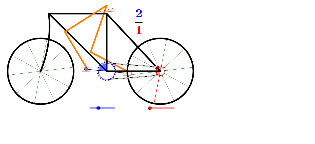
This example demonstrates the mathematical relationship between gear ratios and fractions using a bicycle gear system. It involves core concepts like proportions, fractions, similar triangles, and logic. The construction utilizes GeoGebra commands and objects such as Point, Angle, Segment, CircleSector, Circle, Polygon, Sequence, Vector, Mirror, PolyLine, CircumcircleArc, Translate, Intersect, and Element. It is suitable for middle school and above students studying the application of geometry and algebra, or for physics education on transmission systems.
GeoGebra Commands & Parameters
Point(Circle[A, 2.5 * zr]) → C'Angle(C, A, C') → angSegment(F, E) → lSegment(A, C') → aCircleSector(A, F, Rotate[F, t1, A]) → cCircle(B, wr) → ePolygon(F + v / 5, F + h / 10, F - h / 10) → fth, b, f, gPolygon(E + v / 5, E + h / 10, E - h / 10) → bth, i, j, kSequence(Rotate[fth, t1 + i * 2 * π / fthr, A], i, 1, fthr) → list3Sequence(Rotate[bth, t2 + i * 2 * π / bthr, B], i, 1, bthr) → list4Segment(Mirror[F, A], Mirror[E, B]) → mVector(E, F) → clvMirror(F, A) → F'CircleSector(B, E, Rotate[E, t2, B]) → dMirror(E, B) → E'Vector(F', E') → clv2PolyLine(A, B, G, A, H, G) → nCircumcircleArc(H, H - 3 * v, I) → pTranslate(e, Vector[B, I]) → e'Sequence(Segment[Rotate[D, t2 + i * 2 * π / ws, B], Rotate[E, t2 + i * 2 * π / ws, B]], i, 1, ws) → list1Sequence(Segment[I, Rotate[J, t2 + i * 2 * π / ws, I]], i, 1, ws) → list2Polygon(G + 0.3 * v + h, G + 0.7 * v + h, G + 0.2 * v - h) → poly1, q, r, sCircle(M, 5 * zr) → d_1Circle(K, 6 * zr) → c_1Intersect(c_1, d_1, 2) → LPolygon(C' + 0.5 * h + 0.25 * v, C' + 0.5 * h - 0.25 * v, C' - 0.5 * h - 0.25 * v, C' - 0.5 * h + 0.25 * v) → poly2, b_1, e_1, f_1, g_1PolyLine(K, L, M) → a_1Mirror(C', A) → C''Mirror(poly2, A) → poly2'Circle(N, 5 * zr) → h_1Intersect(c_1, h_1, 2) → OPolyLine(K, O, N) → i_1Segment(A, C'') → j_1Circle(A, r1) → k_1Circle(B, r2) → p_1Sequence(Arc[k_1, Rotate[F, Min[3.141592653589793, Max[0, (clink * i + posModl) / cl1 * π]], A], Rotate[F, Max[0, Min[3.141592653589793, (clink * i + posModl + clink / 2) / cl1 * π]], A]], i, 0, round(cl1 / clink)) → list5Sequence(Arc[p_1, Rotate[E', Min[3.141592653589793, Max[0, (clink * i + posModr) / cl2 * π]], B], Rotate[E', Max[0, Min[3.141592653589793, (clink * i + posModr + clink / 2) / cl2 * π]], B]], i, 0, round(cl2 / clink)) → list7Sequence(Segment[F' + clv2 * Min[1, Max[0, (clink * i + posModb) / l]], F' + clv2 * Min[1, Max[0, (clink * i + posModb + clink / 2) / l]]], i, 0, If[clink * nclink + posModb > l, nclink - 1, nclink]) → list6Sequence(Segment[E + clv * Min[1, Max[0, (clink * i + posModt) / l]], E + clv * Min[1, Max[0, (clink * i + posModt + clink / 2) / l]]], i, 0, If[clink * nclink + posModb > l, nclink - 1, nclink]) → list8Element(list1, Length[list1]) → l_1
AI Drawing Prompt Reference
Draw a bicycle gear system to demonstrate the relationship between gear ratios and fractions. Include two gears, represented by points for axles and sectors for the gears themselves. Use polygons to depict the teeth of the gears. Illustrate the direction of transmission between gears with vectors and the outlines with circles. Connect the teeth with arcs and show the tooth shapes with polygons. Link the axles with line segments and represent the rotation with arcs. Use vectors to indicate the rotation direction and polygons for the rotation paths.
The prompt above was compiled from the original drawing commands and is for reference only.