
Bearings (True and Compass)
Loading the math board and drawing, please wait…
In collections
GCSE Higher Ch8 Transformations & Constructions
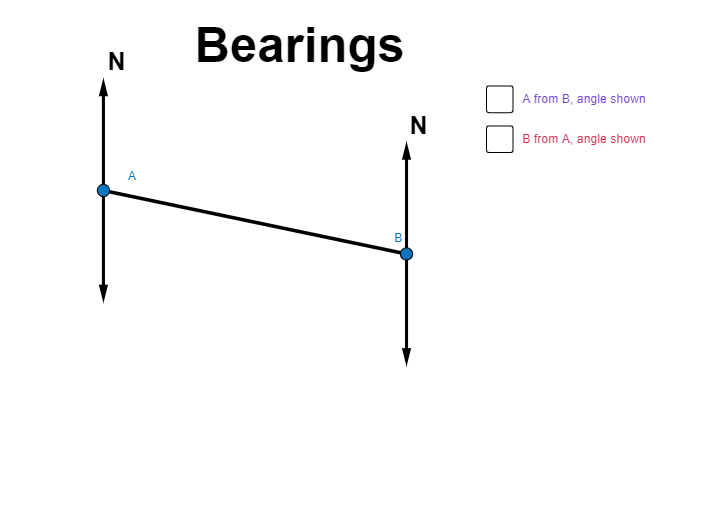
This example demonstrates how to use GeoGebra to draw and calculate the relationship and conversion between true north bearings and compass bearings, involving core math concepts like angle measurement, vectors, geometric transformations, and coordinate systems. Key GeoGebra commands/objects used include Segment, Vector, and Angle for construction, suitable for high school mathematics teaching on applications in navigation and cartography.
GeoGebra Commands & Parameters
Segment(A, B) → aVector(A, C) → uVector(B, D) → vAngle(A, B, D) → αAngle(B, A, C) → βVector(B, E) → wVector(A, F) → zAngle(E, B, A) → ζAngle(A, B, E) → ηAngle(D, B, A) → θ
AI Drawing Prompt Reference
Draw a coordinate system with two direction vectors u and v, and the true north bearings α and β formed by these vectors. Then, draw vectors w and z, which form angles ζ, η, and θ with vectors u and v respectively. Note that u and v represent directions in the geographic coordinate system, while w and z represent directions in the compass coordinate system.
The prompt above was compiled from the original drawing commands and is for reference only.