
A Plane Intersecting a Cube
Loading the math board and drawing, please wait…
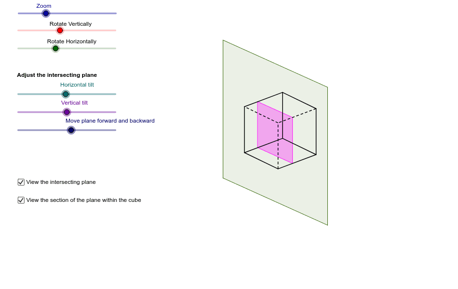
This example demonstrates the geometric shape formed by the intersection of a plane and a cube. It involves core mathematical concepts such as solid geometry, spatial geometry, intersection, and polygons. The construction utilizes commands like Odcinek_3D (3D segment), Element (element), Polygon (polygon), IloczynSkalarny3D (3D dot product), If (conditional statement), RemoveUndefined (remove undefined), Sequence (sequence), and Sort (sort). It is suitable for high school students and teachers studying solid geometry and spatial geometry.
GeoGebra Commands & Parameters
Odcinek_3D(D1, D5, D4, D2) → c, dOdcinek_3D(D1, D2, D5, D4) → e, fOdcinek_3D(D1, D4, D2, D5) → g, hOdcinek_3D(D2, D6, D1, D3) → i, jOdcinek_3D(D2, D3, D6, D1) → k, lOdcinek_3D(D3, D7, D2, D4) → m, nOdcinek_3D(D3, D4, D7, D2) → p, qOdcinek_3D(D4, D8, D3, D1) → s, tOdcinek_3D(D8, D5, D7, D4) → a_1, b_1Odcinek_3D(D8, D7, D4, D5) → c_1, d_1Odcinek_3D(D7, D6, D3, D8) → e_1, f_1Odcinek_3D(D6, D5, D2, D7) → g_1, h_1Element(Join[B10], 1) → C10Element(Join[B10], 2) → D10Element(Join[B10], 3) → E10Element(Join[B11], 1) → C11Element(Join[B11], 2) → D11Element(Join[B11], 3) → E11Element(Join[B12], 1) → C12Element(Join[B12], 2) → D12Element(Join[B12], 3) → E12Element(Join[B13], 1) → C13Element(Join[B13], 2) → D13Element(Join[B13], 3) → E13Element(Join[B14], 1) → C14Element(Join[B14], 2) → D14Element(Join[B14], 3) → E14Polygon(F12, F13, F10, F11) → poly1, f12, f13, f10, f11IloczynSkalarny3D(B14, B15) → C15IloczynSkalarny3D(B15, C17) → E17IloczynSkalarny3D(B15, C18) → E18IloczynSkalarny3D(B15, C19) → E19IloczynSkalarny3D(B15, C20) → E20IloczynSkalarny3D(B15, C21) → E21IloczynSkalarny3D(B15, C22) → E22IloczynSkalarny3D(B15, C23) → E23IloczynSkalarny3D(B15, C24) → E24IloczynSkalarny3D(B15, C25) → E25IloczynSkalarny3D(B15, C26) → E26IloczynSkalarny3D(B15, C27) → E27IloczynSkalarny3D(B15, C28) → E28If((F17 ≥ 0) ∧ (F17 ≤ 1), F17) → G17If((F18 ≥ 0) ∧ (F18 ≤ 1), F18) → G18If((F19 ≥ 0) ∧ (F19 ≤ 1), F19) → G19If((F20 ≥ 0) ∧ (F20 ≤ 1), F20) → G20If((F21 ≥ 0) ∧ (F21 ≤ 1), F21) → G21If((F22 ≥ 0) ∧ (F22 ≤ 1), F22) → G22If((F23 ≥ 0) ∧ (F23 ≤ 1), F23) → G23If((F24 ≥ 0) ∧ (F24 ≤ 1), F24) → G24If((F25 ≥ 0) ∧ (F25 ≤ 1), F25) → G25If((F26 ≥ 0) ∧ (F26 ≤ 1), F26) → G26If((F27 ≥ 0) ∧ (F27 ≤ 1), F27) → G27If((F28 ≥ 0) ∧ (F28 ≤ 1), F28) → G28RemoveUndefined(list1) → list2Sequence(Angle[Element[list2, 1], F14, Element[list2, i]], i, 1, Length[list2]) → list3Sort(list3) → list4Sequence(Sequence[If[Element[list3, j] ≟ Element[list4, i], Element[list2, j]], j, 1, Length[list2]], i, 1, Length[list4]) → list5RemoveUndefined(Join[list5]) → list6Polygon(list6) → wielokąt1
AI Drawing Prompt Reference
Draw the geometric shape formed by the intersection of a cube and a plane, showing the intersection lines and polygons. First, construct the 12 edges of the cube, then the 4 edges of the plane. Connect the intersection points between the cube and the plane to form the intersection lines, and finally use the intersection points to create polygons to display the intersection part between the lines and the cube.
The prompt above was compiled from the original drawing commands and is for reference only.