
3D Vectors and Prism Geometry: Cosine, Subtraction, and Median (Figure 44)
Loading the math board and drawing, please wait…
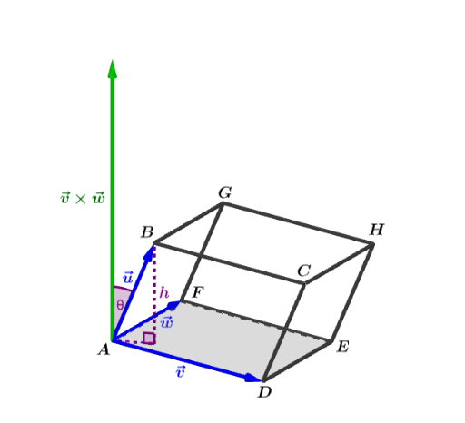
① This GeoGebra example constructs a three-dimensional prism and demonstrates vector operations, cosine relationships, and median values using its vertices, edges, and faces. ② Core mathematical concepts include 3D vectors, vector subtraction, cosine of the angle between vectors, planes and prism surfaces, midpoints, and geometric mean, along with solid geometry elements such as edges, faces, and diagonals. ③ Construction highlights: the Polygon and Prism commands create the base and solid; Vector defines vectors u, v, w; Plane, OrthogonalLine, and Intersect build auxiliary planes and intersection points; Segment connects key points, Angle measures angles, and Midpoint marks midpoints. Objects include E, F, D, A, B, C, H, G, faces like faceABFE, and edges like edgeAE. ④ Suitable for high school to early college students learning solid geometry and vector algebra, serving as a visual aid for 3D vector operations, cosine theorem applications, and geometric mean demonstrations.
GeoGebra Commands & Parameters
Polygon(A, D, E, F) → q1, a, b, c, dPrism(q1, B) → e, C, edgeBF, edgeCG, edgeDH, edgeEF, edgeFG, edgeGH, edgeEH, H, G, faceABFE, faceBCGF, faceCDHG, faceADHE, faceEFGH, edgeAEVector(A, B) → uVector(A, D) → vVector(A, F) → wPlane(A, D, F) → pOrthogonalLine(B, p) → iIntersect(i, p) → ISegment(B, I) → jSegment(I, A) → kAngle(B, I, A) → αMidpoint(j) → NSegment(D, C) → qSegment(B, C) → rSegment(E, H) → sSegment(G, H) → tMidpoint(a) → KMidpoint(d) → MVector(A, P) → lAngle(B, A, P) → θSegment(B, G) → gSegment(C, H) → hSegment(F, G) → nSegment(D, E) → g_1Midpoint(A, B) → LMidpoint(A, P) → JSegment(E, F) → f
AI Drawing Prompt Reference
Construct a 3D prism: start with a base quadrilateral made by points A, D, E, and F, then use point B to form the prism so that the corresponding top vertices align as C, G, and H above D, E, and F respectively. Show the prism’s key edges and faces created by these connections. From point A draw three vectors pointing to B, D, and F. Create an auxiliary plane determined by A, D, and F, drop the perpendicular from B to that plane, and let it meet the plane at I; connect B to I and I to A to form the angle at I. Mark relevant midpoints on the drawn segments in the base, and include segments connecting D–C, B–C, E–H, G–H, and F–G. Also form a segment from A to an indicated point P and define the angle at A using B–A–P as needed for the figure’s angle relationships.
The prompt above was compiled from the original drawing commands and is for reference only.