
3D Pinhole Camera Visualization
Loading the math board and drawing, please wait…
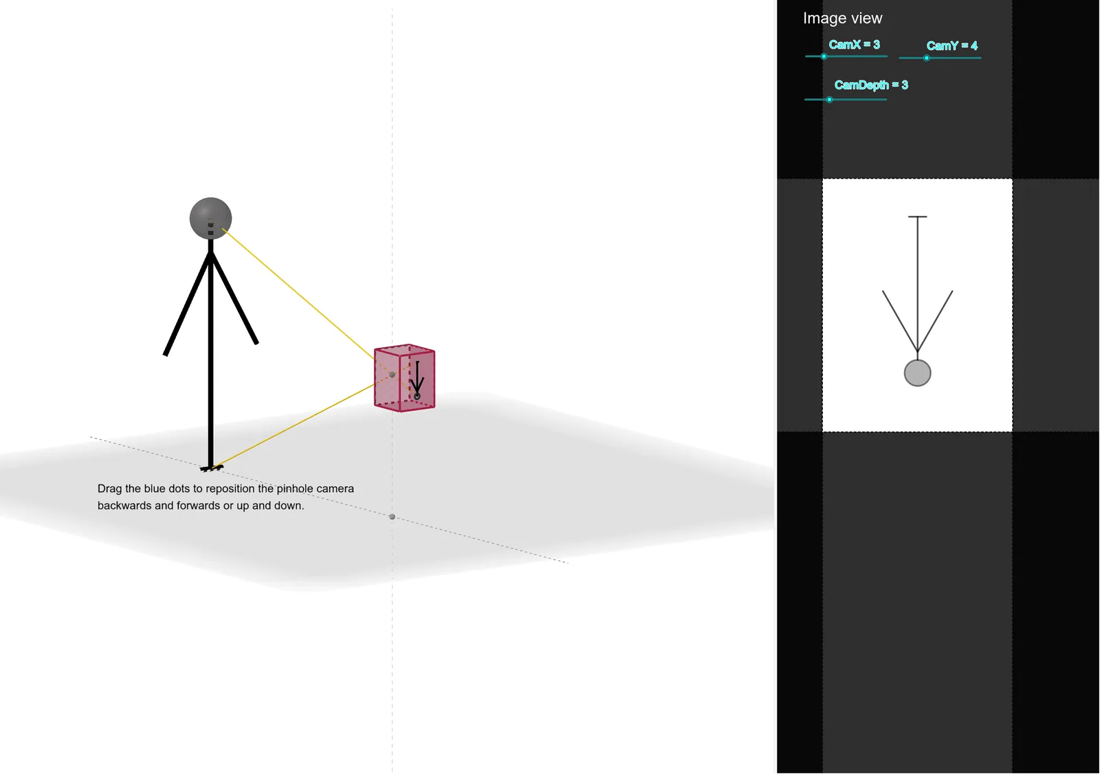
This GeoGebra example presents an interactive 3D pinhole camera model that can be rotated to explore the geometric principles behind pinhole imaging. It demonstrates how light rays from an object pass through a small hole and project onto an image plane, forming an inverted image. The core mathematical concepts involve similar triangles, perspective projection, intersections of lines and planes, and spatial geometry. The construction uses commands such as Segment, Point, OrthogonalLine, Line, Polygon, Prism, Intersect, Sphere, IntersectPath, and Circle to build the camera body, object, and image plane. Adjustable parameters like CamDepth, CamX, and CamY allow dynamic manipulation of the camera position and depth, making it easy to observe how image size and orientation change. This resource is suitable for high school and university students studying solid geometry, similarity, optics, or introductory computer graphics.
GeoGebra Commands & Parameters
Segment(C, D) → gPoint(g) → VOrthogonalLine(V, g, xOyPlane) → g_1Point(g_1) → WOrthogonalLine(W, h_1) → i_1Point(i_1) → ZLine(B, P) → jPolygon(Fr1, Fr4, Fr3, Fr2) → q1, fr1, fr4, fr3, fr2OrthogonalLine(Z, q1) → r_1Prism(q1, (-CamDepth)) → b, H, edge1, edge2, edge3, edge4, edge5, edge6, edge7, edge8, I, J, K, face1, face2, face3, face4, face5Intersect(r_1, p) → I_1Intersect(j, p) → SSphere(B, 1.5) → aSegment(A, B) → fPoint(f) → ESegment(F, E) → hSegment(E, G) → iLine(A, P) → kLine(E, P) → lLine(G, P) → mLine(F, P) → nLine(C, P) → qLine(D, P) → rIntersect(r, p) → LIntersect(q, p) → MIntersect(n, p) → NIntersect(m, p) → OIntersect(l, p) → QIntersect(k, p) → RIntersect(f, a) → T,Line(T, P) → sIntersect(s, p) → USegment(M, L) → tSegment(R, S) → dSegment(Q, O) → eSegment(Q, N) → f_1Line(T, P) → j_1Intersect(j_1, p) → A_1Sphere(S, A_1) → cSegment(B, S) → k_1Segment(V, R) → l_1Segment(F, N) → n_1Segment(G, O) → p_1IntersectPath(p, c) → c_1Circle(SSSS, AA) → s_1Segment(RR, AA) → t_1Segment(MM, LL) → a_1Segment(NNNN, QQ) → b_1Segment(QQ, OO) → f_2
AI Drawing Prompt Reference
Draw a 3D pinhole camera model with the camera body, object, and image plane. Start by constructing the camera body, then place the object and determine the image plane's position. Adjust the camera's depth and position to observe changes in image size and orientation.
The prompt above was compiled from the original drawing commands and is for reference only.