
Pinhole Camera 3D - Draft
Loading the math board and drawing, please wait…
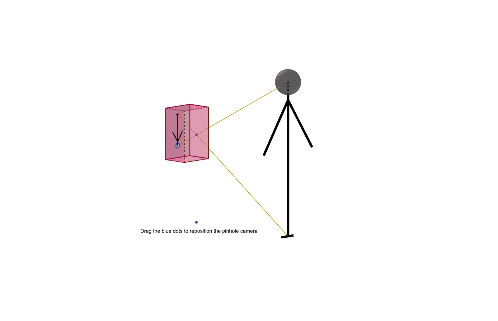
This GeoGebra example provides a 3D visualization of a pinhole camera, demonstrating how light rays from an object pass through a small aperture and form an inverted image on the image plane. The core mathematical concepts involve similar triangles, line-plane intersections, and three-dimensional projection. The construction uses commands such as Segment, Point, OrthogonalLine, Sphere, Polygon, Prism, Plane, Line, Intersect, and IntersectPath to build the camera body, the pinhole, the object, and the image plane, with multiple polygons and prisms representing the camera housing and image frame. Suitable for high school or early college students studying solid geometry, projective geometry, and the mathematical basis of optical imaging, as well as for physics classes explaining the pinhole camera effect.
GeoGebra Commands & Parameters
Segment(C, D) → gPoint(g) → VOrthogonalLine(V, g, xOyPlane) → g_1Point(g_1) → WOrthogonalLine(W, h_1) → i_1Point(i_1) → ZSphere(B, 1.5) → aSegment(A, B) → fPoint(f) → ESegment(F, E) → hSegment(E, G) → iPolygon(Fr1, Fr4, Fr3, Fr2) → q1, fr1, fr4, fr3, fr2Prism(q1, -3) → b, H, edgeFr1H, edgeFr4I, edgeFr3J, edgeFr2K, edgeHI, edgeIJ, edgeJK, edgeHK, I, J, K, faceFr1Fr4IH, faceFr3Fr4IJ, faceFr2Fr3JK, faceFr1Fr2KH, faceHIJKPlane(I, H, K) → pLine(B, P) → jLine(A, P) → kLine(E, P) → lLine(G, P) → mLine(F, P) → nLine(C, P) → qLine(D, P) → rIntersect(r, p) → LIntersect(q, p) → MIntersect(n, p) → NIntersect(m, p) → OIntersect(l, p) → QIntersect(k, p) → RIntersect(j, p) → SIntersect(f, a) → T,Line(T, P) → sIntersect(s, p) → USegment(M, L) → tSegment(R, S) → dSegment(Q, O) → eSegment(Q, N) → f_1Line(T, P) → j_1Intersect(j_1, p) → A_1Sphere(S, A_1) → cSegment(B, S) → k_1Segment(V, R) → l_1Point(i_1) → B_1Segment(F, N) → n_1Segment(G, O) → p_1IntersectPath(p, c) → c_1
AI Drawing Prompt Reference
Draw a 3D pinhole camera model: construct a rectangular prism as the camera body, place a small pinhole point near the center of its front face, and draw a perpendicular line from this point into the camera, with a reference point on this line for the image plane. Place an object in front of the camera, consisting of several segments and points. From multiple key points on the object, draw straight lines to the pinhole, which pass through the aperture and intersect the image plane, yielding a set of intersection points. Connect these points to form an inverted image. Place a sphere on the object, intersecting one of its edges; from the intersection point, draw a line to the pinhole, intersect it with the image plane, and add this extra image point. Finally, draw a circle on the image plane to represent the image outline.
The prompt above was compiled from the original drawing commands and is for reference only.