
三棱锥的截面 by David Matthews
几何画板及绘图内容加载中,请稍等……
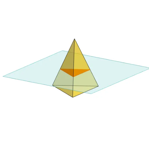
本范例演示了如何通过平面切割三棱锥,并展示了截面的形状变化。涉及的核心数学概念包括立体几何和几何作图。使用了Polygon, PointIn, Translate, Rotate, Pyramid, Plane, IntersectPath, OrthogonalLine等GeoGebra命令。适合高中数学教学和学习。
GeoGebra 命令及参数
Polygon(B + (-2, -2), B + (2, -2), B + (2, 2), B + (-2, 2)) → poly3, e, f, g, iPointIn(poly3) → CTranslate((0, 0, 0), Vector[B, C]) → APolygon(A + (-4, -4), A + (4, -4), A + (4, 4), A + (-4, 4)) → poly1, a, b, c, dRotate(Rotate[Translate[poly1, Vector[A, A + (0, 0, h)]], (90° * s), A + (0, 0, h), yAxis], (90° * t), A, zAxis) → poly2Pyramid(Polygon[(-2, 0, 0), Rotate[(-2, 0, 0), 120°, zAxis], Rotate[(-2, 0, 0), (-(120°)), zAxis]], (0, 0, 4)) → m, face1, face2, face3, edge1, edge2, edge3Rotate(D, 120°, (0, 0, 0)) → EPolygon(D, E, 3, xOyPlane) → poly4, j, k, l, FPointIn(poly2) → GPointIn(poly2) → HPointIn(poly2) → IPlane(G, I, H) → nIntersectPath(n, m) → poly6, poly5, r, a_1, b_1, c_1, K, L_1, O, P, J, L, p, qRotate(m, 0, zAxis) → m'Rotate(m, 0, zAxis) → m'_1OrthogonalLine(A, n) → d_1
AI 绘图提示语参考
绘制一个三棱锥,并用一个平面切割它,观察截面形状的变化。首先画一个底面为正方形的四棱锥,然后围绕z轴旋转生成三棱锥,接着在三棱锥上选择几个点,用这些点定义一个平面,最后与三棱锥相交得到截面。
以上提示语为根据原始绘图命令整理而来,仅供参考。