
正多边形的正弦函数关系可视化
几何画板及绘图内容加载中,请稍等……
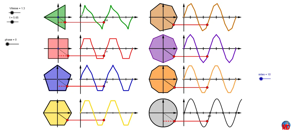
该范例演示如何用正多边形的几何构造来得到与角度相关的正弦函数变化规律,并在图形中观察随边数/相位变化的周期性特征。核心数学概念包括:三角函数(sin)、正多边形的中心角与边长/周长度量、角度相位与参数化、向量/射线与旋转变换、以及与函数图像相对应的几何量追踪。作图要点来自构造摘要中的命令与对象:使用 Sequence 与 If 生成参数序列与条件分支(如相位 phase、边数 sides 的迭代),借助 Rotate、Ray、Line、Segment 构造随角度变化的几何元素;用 Polygon、Circle、Intersect、Point 构成正多边形及其关键交点;通过 Distance、Vector 表示长度与方向信息;借助 Locus 生成变化轨迹(如由位置参数形成的曲线),并结合 Mod、Translate、Mirror 等完成周期性与对称/平移处理(对象如 t、AA、A、B、FF、liste1/liste2 等承载参数与点集);同时用 Perimeter、Line 等量化多边形周长相关量,用于与 sin 函数对应的几何表达。适合高中到大学初级阶段的数学建模、三角函数教学、几何与函数的综合课程,以及对函数与变换直观理解的课堂演示或研究性学习。
GeoGebra 命令及参数
Mod(sides, 4) → aaSequence(K + ((R * cos(i + π / 3 + (phase * π / 6))), (R * sin(i + π / 3 + (phase * π / 6)))), i, 0, 6.28319, 2.0944) → liste2Mod(sides, 2) → nnIf(aa ≟ 1, Rotate[B, π / 5, A], Rotate[B, ((-π)) / 5, A]) → BBIf(aa ≟ 0, BB, F) → FFRotate(B, t, A) → B'Ray(A, B') → kSegment(B, E) → hSegment(A, B') → bSequence(Rotate[FF, i + (phase * π / 10), A], i, 0, 6.28319, (2 * π / 5)) → liste1Polygon(liste1) → pIntersect(k, p) → K_2Intersect(b, p) → DPoint(p, m) → M_1Perimeter(p) → perLine(M_1, xAxis) → aIntersect(a, yAxis) → CCircle(A, R) → cDistance(A, C) → disDistance(B, J) → ddSegment(D, P) → dSegment(F, G) → gVector(G, F) → uVector(I, B) → vSegment(H, A) → iSegment(D, H) → jLocus(P, t) → lieu1Rotate(L, t, K) → L'Rotate(M, 120°, K) → M'Rotate(M, 240°, K) → M'_1Ray(M, M') → a_1Ray(M, M'_1) → l_1Polygon(liste2) → poly2Ray(K, L') → lIntersect(l, poly2) → NSegment(K, N) → d_1Distance(L, JJ) → dtSegment(N, PT) → nLocus(PT, t) → lieu2Sequence(O + ((R * cos(i + π / 4 + (phase * π / 8))), (R * sin(i + π / 4 + (phase * π / 8)))), i, 0, 6.28319, 1.5708) → liste3Rotate(Q, t, O) → Q'Ray(O, Q') → rPolygon(liste3) → poly1Intersect(r, poly1) → SSegment(O, S) → e_1Distance(Q, T) → dcLocus(PC, t) → lieu3Segment(S, PC) → f_1Vector(V, W) → wCircle(Z, R) → g_1Rotate(A_1, t, Z) → B_1Segment(Z, B_1) → h_1Segment(B_1, D_1) → i_1Vector(C_1, G_1) → zVector(E_1, F_1) → u_1Vector(O_1, H_1) → v_1Segment(K_2, A) → j_1Mirror(Q, O) → Q'_1Mirror(L, K) → L'_1Mirror(A_1, Z) → I_1Vector(L'_1, L) → w_1Vector(I_1, A_1) → z_1Vector(Q'_1, Q) → k_1Mirror(A, M) → A'Mirror(K_1, O) → L_{1}Mirror(J_1, Z) → N_{1}Vector(N_{1}, J_1) → m_1Vector(L_{1}, K_1) → n_1Mirror(A, M) → A'_1Mirror(K, M) → K'Mirror(M, K) → M'_2Vector(M'_2, M) → q_1Segment(Q_1, S) → r_1Segment(P_1, N) → s_1Segment(R_1, B_1) → t_1Sequence(V + (i, 0), i, 0, 14, 1.5708) → liste4Sequence(O_1 + (i, 0), i, 0, 14, 1.5708) → liste5Sequence(E_1 + (i, 0), i, 0, 14, 1.5708) → liste6Sequence(C_1 + (i, 0), i, 0, 14, 1.5708) → liste7Sequence(Text[i / 2.5 + "π", Element[liste7, i] - (0.51, 0.95)], i, 0, Length[liste5], 5) → liste9Sequence(Text[i / 2.5 + "π", Element[liste6, i] - (0.51, 0.95)], i, 0, Length[liste5], 5) → liste10Sequence(Text[i / 2.5 + "π", Element[liste4, i] - (0.51, 0.95)], i, 0, Length[liste5], 5) → liste11Polygon(V_{1}, Z_{1}, A_2, W_{1}) → q1, f_2, g_2, a_2, h_2Polygon(W_{1}, B_2, C_2, A_2) → q2, i_2, b_2, c_2, j_2Polygon(B_2, D_2, E_2, C_2) → q3, k_2, d_2, e_2, l_2Polygon(D_2, F_2, G_2, E_2) → q4, m_2, n_2, p_2, q_2Translate(q_1, Vector[K, V]) → u_2Vector(V - (0, 3.5), V + (0, 3.5)) → v_2Vector(O_1 - (0, 3.15), O_1 + (0, 3.45)) → w_2Vector(E_1 - (0, 3.5), E_1 + (0, 3.5)) → r_2Vector(C_1 - (0, 3.15), C_1 + (0, 3.5)) → s_2Sequence(Text[i / 2.5 + "π", Element[liste5, i] - (0.51, 0.95)], i, 0, Length[liste5], 5) → liste8Vector(H_2 - (R, 0), H_2 + (R, 0)) → t_2Vector(H_2 - (0, R), H_2 + (0, R)) → u_3Sequence(Rotate[H_2 + (R, 0), i + (phase * π / 12), H_2], i, 0, 6.28319, (2 * π / 6)) → l1Polygon(l1) → poly3Vector(I_2 - (0, 3.5), I_2 + (0, 3.5)) → v_3Vector(I_2, (14, y(H_2))) → w_3Sequence(I_2 + (i, 0), i, 0, 14, 1.5708) → liste6bRotate(H_2 + (R, 0), t, H_2) → J_2Ray(H_2, J_2) → f_3Intersect(f_3, poly3) → L_2Segment(H_2, L_2) → g_3Locus(M_2, t) → lieu4Segment(L_2, M_2) → h_3Vector(L_1 - (0, R), L_1 + (0, R)) → a_3Vector(N_2 - (0, R), N_2 + (0, R)) → b_3Vector(O_2 - (0, R), O_2 + (0, R)) → c_3Vector(L_1 - (R, 0), L_1 + (R, 0)) → d_3Vector(N_2 - (R, 0), N_2 + (R, 0)) → e_3Vector(O_2 - (R, 0), O_2 + (R, 0)) → i_3Vector(P_2 - (0, R), P_2 + (0, R)) → j_3Vector(Q_2 - (0, R), Q_2 + (0, R)) → k_3Vector(R_2 - (0, R), R_2 + (0, R)) → l_3Vector(P_2, (39, y(P_2))) → m_3Vector(Q_2, (39, y(Q_2))) → n_3Vector(R_2, (39, y(R_2))) → p_3Sequence(Rotate[L_1 + (R, 0), i + (phase * π / 14), L_1], i, 0, 6.28319, (2 * π / 7)) → l2Sequence(Rotate[N_2 + (R, 0), i + (phase * π / 16), N_2], i, 0, 6.28319, (2 * π / 8)) → l3Sequence(Rotate[O_2 + (R, 0), i + (phase * π / ((2 * sides))), O_2], i, 0, 6.28319, (2 * π / sides)) → l4Polygon(l2) → poly4Sequence(P_2 + (i, 0), i, 0, 14, 1.5708) → liste6cSequence(Q_2 + (i, 0), i, 0, 14, 1.5708) → liste6dSequence(R_2 + (i, 0), i, 0, 14, 1.5708) → liste6ePolygon(l3) → poly5Polygon(l4) → poly6Rotate(L_1 + (R, 0), t, L_1) → S_2Rotate(N_2 + (R, 0), t, N_2) → T_2Rotate(O_2 + (R, 0), t, O_2) → U_2Ray(L_1, S_2) → q_3Ray(N_2, T_2) → r_3Ray(O_2, U_2) → s_3Intersect(q_3, poly4) → V_2Intersect(r_3, poly5) → W_2Intersect(s_3, poly6) → Z_2Segment(L_1, V_2) → t_3Segment(N_2, W_2) → f_4Segment(O_2, Z_2) → g_4Segment(V_2, A_3) → h_4Segment(W_2, B_3) → i_4Segment(Z_2, C_3) → j_4Locus(A_3, t) → lieu5Locus(B_3, t) → lieu6Locus(C_3, t) → lieu7Polygon(liste3) → poly7Polygon(liste2) → q5Polygon(liste1) → poly8Polygon(l1) → poly9Polygon(l2) → poly10Polygon(l4) → poly11
AI 绘图提示语参考
在同一坐标系中,以某点为中心先画出以不同相位旋转生成的正多边形,令多边形顶点随参数等角度连续变化;连接产生用于截取的射线与线,再与该多边形相交得到关键交点。以圆心与该相交结果作距离度量,并取沿参数变化的某个对应点绘制轨迹曲线,展现类正弦的周期性。重复另一组不同初始角与步长的参数设置,构造另一正多边形与相交点,并同样生成对应的轨迹曲线形成对比,同时保留中心点、构造线和相交线段等几何关系。
以上提示语为根据原始绘图命令整理而来,仅供参考。