
杠杆原理演示
几何画板及绘图内容加载中,请稍等……
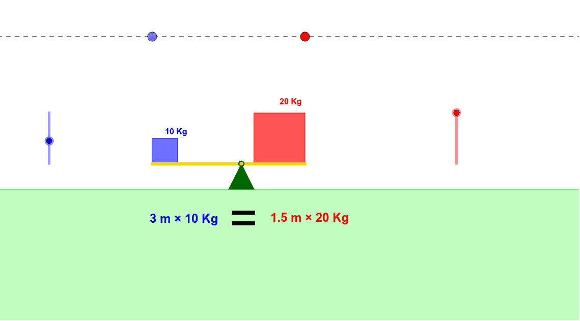
①本范例通过动态演示杠杆的平衡原理,直观展示力矩与支点的关系;②涉及核心数学概念包括力矩计算、向量应用、几何变换与不等式分析;③作图要点提炼自构造摘要,运用了Point, Intersect, Ray, OrthogonalLine, Circle, Segment, Midpoint, Angle, Distance, Polygon, If, Rotate等GeoGebra命令与对象;④适合高中物理与数学教学,用于理解力学原理与几何作图方法。
GeoGebra 命令及参数
Point(g) → GPoint(g) → FIntersect(g, h) → DRay(D, G) → kPoint(k) → IOrthogonalLine(I, k) → mIntersect(m, f_1) → SIntersect(g, i) → ERay(E, F) → jPoint(j) → HOrthogonalLine(H, j) → l_1Intersect(l_1, f_1) → TIntersect(d, m) → KCircle(K, f) → qIntersect(d, l_1) → JCircle(J, e) → pSegment(J, K) → nIntersect(q, n, 1) → MMidpoint(M, K) → RIntersect(p, n, 1) → L_1Midpoint(J, L_1) → LAngle(A, T, S) → γAngle(A, S, T) → βDistance(R, A) → RADistance(L, A) → LAPolygon(A, B, C) → poly1, c, a, bPolygon(J, L_1, 4) → poly2, r_1, s, t, a_1, N, OPolygon(M, K, 4) → poly3, b_1, c_1, d_1, e_1, P, QIf(tt < 0, (-β), If[tt ≟ 0, 0*°, γ]) → αRotate(poly2, α, A) → poly2'Rotate(J, α, A) → J'Rotate(K, α, A) → K'Segment(J', K') → n'Rotate(poly3, α, A) → poly3'Segment(A, S) → g_1Segment(A, T) → h_1If(tt < -1, (-β), If[tt < 1, ((γ + β) / 2 * tt) + (γ - β) / 2, γ]) → θRotate(N, α, A) → N'Rotate(Q, α, A) → Q'Distance(L, A) → lDistance(R, A) → rIf(tt < 0, "<", If[tt ≟ 0, "=", ">"]) → text5
AI 绘图提示语参考
画一个杠杆原理演示图:一条水平基线上固定支点,从支点向两侧延伸两条射线,在射线上任取点并作垂线与另一固定线相交,得到两个投影点;以这两点为圆心分别作圆,圆与连接两投影点的线段相交,取中点作为力臂端点;在支点两侧各构建一个正方形,随一个控制参数旋转,旋转角度由条件表达式决定;同时显示两力臂长度、夹角及一个随参数变化的不等号(<、=、>),直观展示力矩平衡与不平衡状态。
以上提示语为根据原始绘图命令整理而来,仅供参考。