
截面与相对位置
几何画板及绘图内容加载中,请稍等……
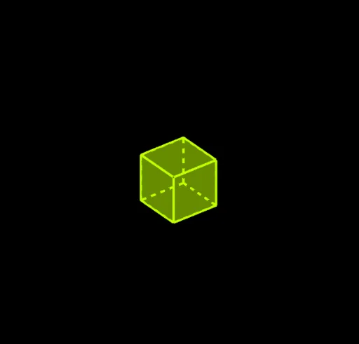
①本范例演示了三维几何体(如立方体)的截面形状及其与几何体相对位置关系的动态变化;②涉及的核心数学概念包括多边形、相似三角形、立体几何、几何作图;③作图要点提炼自构造摘要,使用了Polygon(多边形)、Intersect(交点)、OrthogonalLine(垂线)、Point(点)、Plane(平面)、CircleArc(圆弧)、Circle(圆)、Line(直线)、Segment(线段)、PointIn(点在对象上)、Cube(立方体)等GeoGebra命令/对象;④适合高中及以上学段学习立体几何、几何作图及空间想象能力的学生,也可用于相关课题的演示与探究。
GeoGebra 命令及参数
Polygon(C, D, B, A) → q1, c, d, b, aIntersect(b, yAxis) → EIntersect(c, yAxis) → FIntersect(xAxis, d) → GIntersect(a, xAxis) → HOrthogonalLine(E, xOyPlane) → fOrthogonalLine(G, xOyPlane) → gOrthogonalLine(F, xOyPlane) → hOrthogonalLine(H, xOyPlane) → iPoint(f) → IPoint(yAxis) → JPlane(E, J, I) → eCircleArc(E, I, J) → k_2Point(k_2) → P_2Plane(A, B, P_2) → jCircle(A, 4, j) → pCircle(B, 4, j) → qLine(P_2, b) → lIntersect(l, p) → L, MIntersect(l, q) → N, OPolygon(A, B, N, P_2, L) → poly1, a_1, b_1, n, k_5, l_1Point(i) → PPoint(xAxis) → QCircleArc(H, Q, P) → k_3Point(k_3) → P_3Plane(C, A, P_3) → mLine(P_3, a) → sCircle(C, 4, m) → tCircle(A, 4, m) → c_1Intersect(s, t) → S, TIntersect(s, c_1) → U, VPolygon(C, A, U, P_3, S) → poly2, c_2, a_2, u, r_1, s_1Point(g) → WPoint(xAxis) → ZCircleArc(G, W, Z) → k_1Point(k_1) → P_1Plane(B, D, P_1) → oLine(P_1, d) → f_1Circle(B, 4, o) → e_1Circle(D, 4, o) → g_1Intersect(f_1, e_1) → B_1, C_1Intersect(f_1, g_1) → D_1, E_1Polygon(B, D, D_1, P_1, B_1) → poly3, b_2, d_2, h_1, i_1, j_1Point(h) → F_1Point(yAxis) → G_1CircleArc(F, F_1, G_1) → k_4Point(k_4) → P_4Plane(D, C, P_4) → kLine(P_4, c) → rCircle(D, 4, k) → d_1Circle(C, 4, k) → p_1Intersect(r, d_1) → K, RIntersect(r, p_1) → A_1, H_1Point(r) → I_1Polygon(D, C, A_1, I_1, K) → poly4, d_3, c_3, m_1, n_1, k_6Point(zAxis) → J_1Point(zAxis) → K_1Segment(J_1, K_1) → q_1PointIn(poly2) → A_2PointIn(poly2) → B_2PointIn(poly2) → C_2PointIn(poly2) → D_2PointIn(poly1) → E_2PointIn(poly1) → F_2PointIn(poly1) → G_2PointIn(poly1) → H_2PointIn(poly3) → I_2PointIn(poly3) → J_2PointIn(poly3) → K_2PointIn(poly3) → L_2Polygon(I_2, J_2, K_2, L_2) → q4, r_2, s_2, t_2, e_2PointIn(poly4) → M_2PointIn(poly4) → N_2PointIn(poly4) → O_2Point(zAxis) → R_2PointIn(poly4) → S_2Polygon(N_2, O_2, S_2, M_2) → q5, f_3, o_2, g_3, h_3Polygon(F_2, G_2, H_2, E_2) → q6, i_3, j_3, l_3, m_3Polygon(B_2, C_2, D_2, A_2) → q7, n_3, p_3, q_3, r_3Point(zAxis) → L_1Plane(L_1, xOyPlane) → wPointIn(w) → R_1PointIn(w) → S_1Point(Circle[S_1, Distance[R_1, S_1], Segment[R_1, S_1]]) → T_1Cube(R_1, S_1, T_1) → u_1, U_1, face5, face6, edge2, edge1, edge4, edge6, edge3, edge8, edge10, edge9, V_1, edge5, edge11, edge7, edge12, W_1, Z_1, T_2, face1, face3, face2, face4PointIn(q1) → U_2PointIn(q1) → V_2PointIn(q1) → W_2PointIn(q1) → Z_2Point(zAxis) → B_3Segment(A_3, B_3) → s_3Point(c_2) → C_3Line(C_3, s_3) → t_3Segment(A_3, C_3) → a_3Point(t_3) → D_3Line(D_3, a_3) → b_3Line(B_3, b_3) → e_3Intersect(t_3, e_3) → E_3Point(t_3) → F_3Line(F_3, b_3) → t_1Point(b_3) → M_1Intersect(t_1, zAxis) → N_1Intersect(b_1, j_1) → O_1Point(b_2) → Q_1Point(d_3) → Q_2OrthogonalLine(O_1, q1) → f_2OrthogonalLine(Q_2, q1) → g_2OrthogonalLine(Q_1, q1) → h_2Intersect(e_3, h_2) → G_3Intersect(t_1, h_2) → H_3Segment(O_1, A_3) → i_2Line(N_1, i_2) → j_2Line(B_3, i_2) → l_2Intersect(f_2, j_2) → I_3Intersect(g_2, j_2) → J_3Intersect(l_2, g_2) → L_3Segment(D_3, F_3) → m_2Segment(C_3, E_3) → n_2Point(m_2) → P_5Point(n_2) → P_6Plane(P_5, xOyPlane) → vPointIn(v) → O_3Polygon(O_3, P_5, 4, xOyPlane) → poly5, p_2, q_2, f_4, g_4, Q_3, R_3Plane(P_6, xOyPlane) → o_1PointIn(o_1) → K_3Polygon(K_3, P_6, 4, xOyPlane) → poly6, h_4, i_4, j_4, l_4, T_3, U_3PointIn(poly5) → N_3PointIn(poly5) → M_3PointIn(poly5) → V_3PointIn(poly5) → W_3Polygon(M_3, N_3, W_3, V_3) → q2, m_4, n_4, w_3, v_3OrthogonalLine(M_3, poly6) → p_4OrthogonalLine(V_3, poly6) → q_4OrthogonalLine(W_3, poly6) → r_4OrthogonalLine(N_3, poly6) → s_4Intersect(q_4, poly6) → Z_3Intersect(p_4, poly6) → A_4Intersect(r_4, poly6) → B_4Intersect(s_4, poly6) → C_4Polygon(A_4, C_4, B_4, Z_3) → q3, a_4, c_4, b_4, z_3Intersect(edge3, edge2) → D_4Intersect(edge10, edge12) → E_4Segment(D_4, E_4) → t_4Intersect(edge4, edge6) → F_4Segment(E_4, F_4) → d_4Point(edge9) → G_4Segment(F_4, G_4) → e_4Point(j_3) → H_4Point(l_3) → I_4Segment(H_4, I_4) → f_5Intersect(i_3, j_3) → J_4Segment(I_4, J_4) → g_5Intersect(m_3, i_3) → K_4Segment(J_4, K_4) → h_5Intersect(r_3, q_3) → L_4Point(p_3) → M_4Segment(L_4, M_4) → i_5Point(p_3) → N_4Intersect(r_3, n_3) → O_4Segment(N_4, O_4) → j_5Segment(N_4, M_4) → l_5Intersect(r_2, s_2) → Q_4PointIn(poly3) → R_4Segment(Q_4, R_4) → m_5Intersect(s_2, t_2) → S_4Point(r_2) → T_4Segment(S_4, T_4) → n_5Segment(R_4, S_4) → p_5Point(v_3) → U_4Point(v_3) → V_4Segment(U_4, V_4) → q_5Intersect(n_4, w_3) → W_4Segment(W_4, V_4) → r_5Intersect(m_4, n_4) → Z_4Segment(W_4, Z_4) → s_5Intersect(a_4, z_3) → A_5Point(z_3) → B_5Intersect(c_4, b_4) → C_5Intersect(a_4, c_4) → D_5Intersect(h_3, g_3) → E_5Point(g_3) → F_5Segment(E_5, F_5) → c_5Intersect(f_3, h_3) → G_5Segment(F_5, G_5) → d_5Intersect(f_3, o_2) → H_5Segment(G_5, H_5) → e_5Point(z_3) → I_5Point(z_3) → J_5Segment(I_5, J_5) → t_5Point(b_4) → K_5Segment(J_5, K_5) → a_5Point(c_4) → L_5Segment(K_5, L_5) → b_5Intersect(edge9, edge3) → M_5Intersect(edge6, edge2) → N_5Segment(M_5, N_5) → f_6Intersect(edge11, edge7) → O_5Segment(N_5, O_5) → g_6Point(edge4) → Q_5Segment(O_5, Q_5) → h_6Intersect(edge5, edge1) → R_5Intersect(f_6, edge3) → S_5Segment(R_5, S_5) → i_6Intersect(f_6, edge2) → T_5Segment(S_5, T_5) → j_6Intersect(h_6, g_6) → U_5Segment(T_5, U_5) → l_6Intersect(edge5, edge11) → V_5Segment(U_5, R_5) → m_6
AI 绘图提示语参考
绘制一个立方体及其三个不同平面的截面。首先,绘制一个立方体,然后分别在三个不同的平面上绘制截面多边形。首先在xOy平面上绘制截面多边形,接着在yOz和平面xOz上绘制截面多边形。最后,确保每个截面多边形都与立方体的相应面相交。
以上提示语为根据原始绘图命令整理而来,仅供参考。