
Wrap Up (Part 6): Exploring Rotations in the Coordinate Plane
Loading the math board and drawing, please wait…
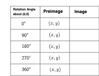
This GeoGebra example demonstrates a systematic exploration of rotations in the coordinate plane, using constructed parallelograms, midpoints, intersections, and segments to visualize how points and polygons transform under rotation. Core mathematical concepts include coordinate geometry, rotation transformations, matrix representation, and properties of parallelograms and polygons. The construction employs GeoGebra commands such as Polygon, Point, Midpoint, Intersect, and Segment, creating base points A, B, C, D and auxiliary points E through Z, along with text objects text1-text8 for labeling and a slider q1 to control the rotation angle. This resource is suitable for upper secondary or early university students learning coordinate geometry and linear transformations, and serves as an interactive teaching tool for instructors to illustrate rotation formulas and matrix operations visually.
GeoGebra Commands & Parameters
Polygon(A, B, C, D) → q1, a, b, c, dPoint(d) → EPoint(b) → FMidpoint(a) → GIntersect(a, d) → HIntersect(a, b) → IIntersect(c, d) → JIntersect(b, c) → KMidpoint(G, H) → LMidpoint(G, I) → MMidpoint(J, K) → NMidpoint(N, J) → OMidpoint(N, K) → PSegment(L, O) → gSegment(N, G) → hSegment(P, M) → iMidpoint(H, D) → QPoint(d) → RPoint(d) → SPoint(d) → TPoint(d) → UPoint(b) → VPoint(b) → WPoint(b) → ZPoint(b) → A_1Point(b) → B_1Segment(R, B_1) → fSegment(A_1, S) → jSegment(Q, Z) → kSegment(T, W) → lSegment(U, V) → m
AI Drawing Prompt Reference
Construct a parallelogram on a coordinate plane using four given corner points, and include an adjustable rotation angle parameter. Determine several auxiliary intersection points by intersecting specific pairs of lines defined by the parallelogram’s vertices, then compute multiple midpoints from selected intersection points and vertices. Connect the resulting midpoints with segments to form the main rotation-related line structure, ensuring that segments link endpoints coming from the same midpoint group and another midpoint pair. Finally, add extra segments that connect from replicated corresponding points associated with the original vertices, so the figure visually indicates how corresponding edges relate under rotation.
The prompt above was compiled from the original drawing commands and is for reference only.