
Visual Sequence Generator (v3)
Loading the math board and drawing, please wait…
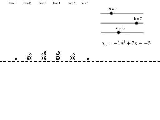
This example demonstrates how to generate visual patterns based on a given quadratic function. It involves core math concepts like quadratic functions, sequences and series, 2D vectors, and function graphing. Construction highlights include using GeoGebra commands like Line and If, along with objects such as a, b, c. Suitable for high school mathematics education or exploration by math enthusiasts.
GeoGebra Commands & Parameters
Line(A, B) → fIf(s(1) ≥ 0, Sequence[Circle[(Mod[n, 2], floor(n / 2 + 0.5)), 0.3], n, 1, s(1)]) → L_2If(s(1) < 0, Sequence[Circle[(Mod[abs(n), 2], (-floor(abs(n) / 2 + 0.5))), 0.3], n, -1, s(1), -1]) → L_3If(s(2) ≥ 0, Sequence[Circle[(Mod[n, 2] + 6, floor(n / 2 + 0.5)), 0.3], n, 1, s(2)]) → L_4If(s(3) ≥ 0, Sequence[Circle[(Mod[n, 2] + 12, floor(n / 2 + 0.5)), 0.3], n, 1, s(3)]) → L_5If(s(4) ≥ 0, Sequence[Circle[(Mod[n, 2] + 18, floor(n / 2 + 0.5)), 0.3], n, 1, s(4)]) → L_6If(s(5) ≥ 0, Sequence[Circle[(Mod[n, 2] + 24, floor(n / 2 + 0.5)), 0.3], n, 1, s(5)]) → L_7If(s(2) < 0, Sequence[Circle[(Mod[abs(n), 2] + 6, (-floor(abs(n) / 2 + 0.5))), 0.3], n, -1, s(2), -1]) → L_8If(s(3) < 0, Sequence[Circle[(Mod[abs(n), 2] + 12, (-floor(abs(n) / 2 + 0.5))), 0.3], n, -1, s(3), -1]) → L_9If(s(4) < 0, Sequence[Circle[(Mod[abs(n), 2] + 18, (-floor(abs(n) / 2 + 0.5))), 0.3], n, -1, s(4), -1]) → L_{10}If(s(5) < 0, Sequence[Circle[(Mod[abs(n), 2] + 24, (-floor(abs(n) / 2 + 0.5))), 0.3], n, -1, s(5), -1]) → L_{11}If(s(6) ≥ 0, Sequence[Circle[(Mod[n, 2] + 30, floor(n / 2 + 0.5)), 0.3], n, 1, s(6)]) → L_1If(s(6) < 0, Sequence[Circle[(Mod[abs(n), 2] + 30, (-floor(abs(n) / 2 + 0.5))), 0.3], n, -1, s(6), -1]) → L_{12}
AI Drawing Prompt Reference
Create a visual pattern generator based on a quadratic function, demonstrating core math concepts. Start by drawing a base line, then generate a series of circles whose positions and quantities depend on input parameters. For positive parameters, arrange the circles along the positive x-axis, and for negative parameters, arrange them along the negative x-axis. Keep the size and spacing of the circles consistent to form a regular pattern. The overall construction is divided into multiple parts, each corresponding to a parameter, displayed sequentially from left to right.
The prompt above was compiled from the original drawing commands and is for reference only.