
Views of a Cube: Spatial Visualization and Geometric Construction
Loading the math board and drawing, please wait…
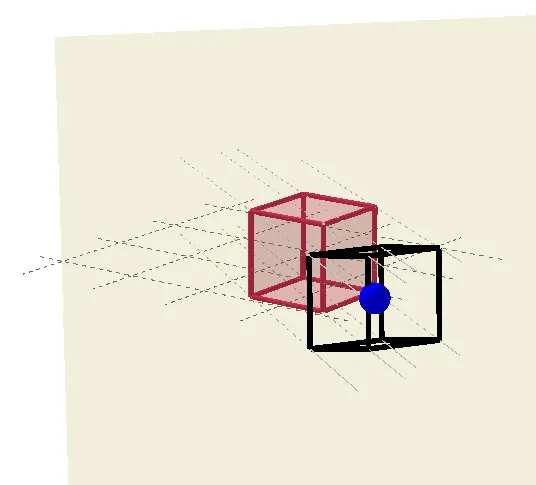
This GeoGebra example dynamically displays a cube from multiple perspectives, showing how a 3D solid projects onto a plane and how auxiliary sections reveal its internal structure. The core mathematical concepts involve solid geometry, cube properties, spatial point-line-plane relationships, and the use of orthogonal planes and lines to create cross-sections. The construction employs commands such as Point, Cube, Dilate, OrthogonalPlane, OrthogonalLine, Intersect, and Segment, generating vertices, edges, faces, and auxiliary points (G', H, I, J, K). Dilate is used for scaling transformations, OrthogonalPlane and OrthogonalLine create perpendicular reference elements, and Intersect with Segment builds the final visible framework. This is suitable for high school or early college students to enhance spatial reasoning, understand projection principles, and practice geometric construction, and it serves as an effective visual aid for classroom instruction.
GeoGebra Commands & Parameters
Point(Circle[(1, -1, -1), Distance[(-1, -1, -1), (1, -1, -1)], Segment[(-1, -1, -1), (1, -1, -1)]]) → APointIn(Sphere[(0, 0), 5]) → GCube((-1, -1, -1), (1, -1, -1), A) → a, B, faceABFE, faceCDEF, edge2, edge1, edge4, edgeAB, edge3, edgeBF, edgeCF, edgeCD, C, edge5, edgeDE, edgeAE, edgeEF, D, E, F, face1, face3, face2, face4Dilate(G, 0.5) → G'OrthogonalPlane(G, Segment[G, G']) → pOrthogonalLine(D, p) → fOrthogonalLine(C, p) → gOrthogonalLine(F, p) → hOrthogonalLine(E, p) → iOrthogonalLine(A, p) → jOrthogonalLine(B, p) → kOrthogonalLine(H, p) → lOrthogonalLine(I, p) → mIntersect(g, p) → JIntersect(l, p) → KIntersect(f, p) → LIntersect(i, p) → MIntersect(j, p) → NIntersect(k, p) → OIntersect(m, p) → PIntersect(h, p) → QSegment(J, Q) → nSegment(M, Q) → qSegment(Q, M) → rSegment(O, Q) → tSegment(K, J) → bSegment(P, K) → cSegment(P, N) → dSegment(N, O) → eSegment(O, K) → f_1Segment(J, L) → g_1Segment(L, P) → h_1Segment(L, M) → i_1Segment(M, N) → j_1
AI Drawing Prompt Reference
Draw a cube with its projection from multiple perspectives. The cube consists of two parallel quadrilaterals and several rectangles, with one vertex near the origin. Introduce several auxiliary lines inside the cube, perpendicular to one of its faces, creating several intersection points on the face. Connect these points to form a grid of auxiliary lines, revealing the internal structure of the cube.
The prompt above was compiled from the original drawing commands and is for reference only.