
Vectors: Magnitude, Angle & Bearing Visualization
Loading the math board and drawing, please wait…
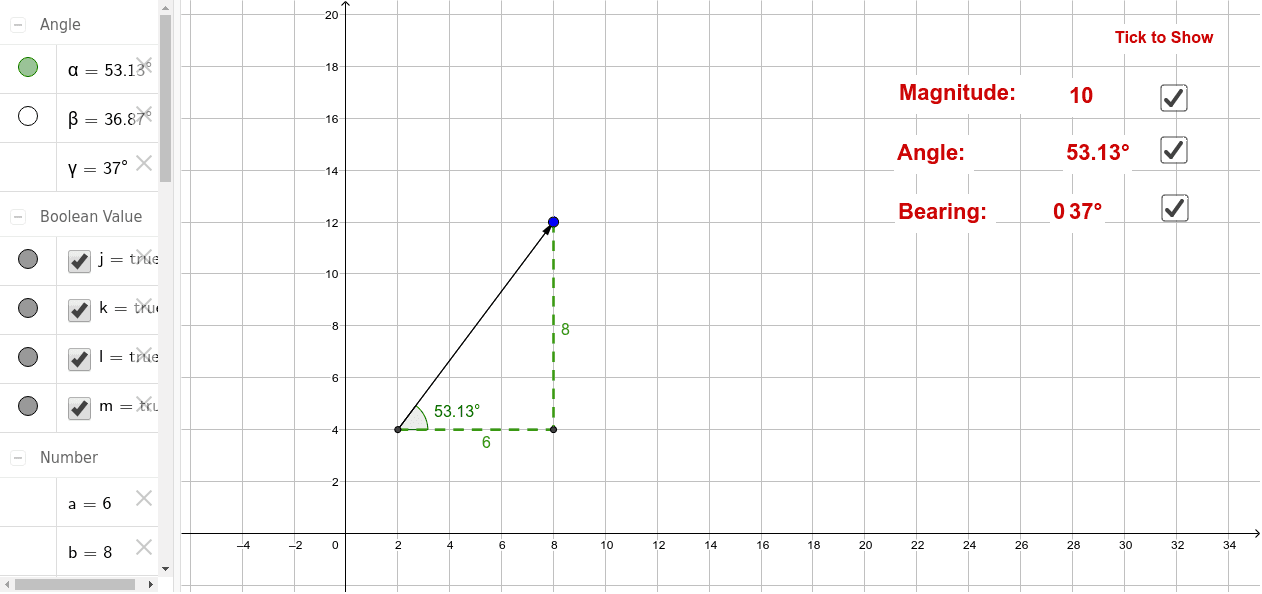
① This GeoGebra example dynamically illustrates the relationships among a vector's magnitude (length), its direction angle (with the positive x-axis), and its bearing (typically measured from north or south), providing an intuitive geometric representation. ② Core mathematical concepts include vector definition, magnitude calculation, conversion between direction angle and bearing, and vector decomposition into horizontal and vertical components. ③ Construction highlights: uses the Vector command to create vectors, Segment for auxiliary lines, Angle to label angles, and Point to define key points; objects include vector u, points A, B, C, D, and multiple angles α, β, γ with text labels, allowing real-time updates via sliders or inputs. ④ Suitable for high school or introductory college mathematics, especially for analytic geometry, vector operations, and trigonometry applications, as well as for demonstrating bearing concepts in navigation or engineering.
GeoGebra Commands & Parameters
Vector(A, C) → uSegment(A, C) → fSegment(C, D) → gSegment(A, D) → hAngle(D, A, C) → αPoint(Circle[A, 2]) → BSegment(A, B) → iAngle(C, A, B) → β
AI Drawing Prompt Reference
Draw a vector visualization diagram: start from an origin point, draw a vector pointing to the upper right, with its length representing magnitude. From the vector's endpoint, drop a perpendicular line to the horizontal axis, forming a right triangle. At the origin, label the angle between the vector and the horizontal axis, and also draw an adjustable auxiliary segment from the origin, creating another angle with the vector to show the relationship between direction angle and bearing. All angles and segment lengths should be adjustable via sliders.
The prompt above was compiled from the original drawing commands and is for reference only.