
Vector–Line–Intersection Construction with 3D/Prism Context
Loading the math board and drawing, please wait…
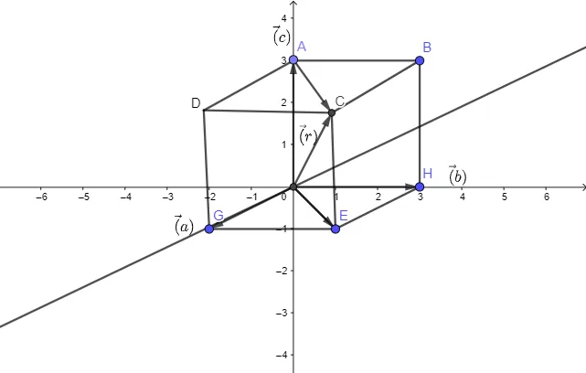
This example demonstrates how to construct a structured geometric diagram in both 2D/3D space by combining vectors, lines, and intersection points, and by using text annotations to clarify the relationships. The key mathematical concepts are vectors (directional geometric representation), lines and their intersections (geometric constraints), and an extended 3D context that may involve solid-like elements such as cylinder/prism settings. Construction highlights: GeoGebra commands are used to build foundational objects step-by-step—Point to create key points (e.g., A_1, B, D_1, D_2, E_1, F, G, H, C), Line to define supporting lines (e.g., i, j, k, l), Vector to display directional vectors (e.g., f, E, m, n, p, q, v, g, u, c), and Intersect to compute intersection points that enforce the geometric constraints (e.g., objects labeled D, E, D_2). Segment is used to connect relevant points for edges or reference geometry, while text1–text4 provide labeling and explanatory marks. Suitable for high school to early undergraduate lessons, especially for visualizing vector ideas alongside geometric constraints and diagram-based modeling.
GeoGebra Commands & Parameters
Point(yAxis) → A_1Segment(A_1, B) → fSegment(A_1, D_2) → DSegment(D_2, D_1) → iIntersect(xAxis, yAxis) → E_1Line(E_1, F) → jSegment(D_2, G) → kSegment(B, H) → lSegment(D_1, E) → mSegment(G, E) → nSegment(E, H) → pSegment(E_1, E) → qVector(E_1, E) → vPoint(yAxis) → AVector(E_1, A) → wVector(E_1, G) → aVector(E_1, H) → bIntersect(i, m) → CSegment(C, B) → gVector(E_1, C) → uVector(A, C) → c
AI Drawing Prompt Reference
Draw a geometric diagram in 2D or 3D space using vectors, lines, and intersection points. Key points include A_1, B, D_2, D_1, E_1, F, G, H, C. Lines include i, j, k, l. Vectors include f, E, m, n, p, q, v, g, u, c. Intersection points such as D, E, D_2, E_1. Connect these points to form edges and reference geometry. Use text annotations to clarify relationships. Suitable for high school or early undergraduate lessons on vectors and geometric constraints.
The prompt above was compiled from the original drawing commands and is for reference only.