
Vector Addition via Parallelogram Construction
Loading the math board and drawing, please wait…
In collections
Basic Constructions
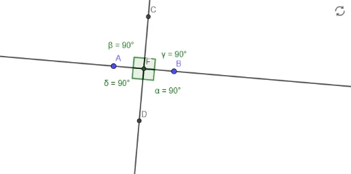
This example demonstrates how to construct a parallelogram to represent vector addition geometrically. It involves core math concepts like vectors, parallelograms, vector representation, and trigonometry. The construction uses GeoGebra commands/objects such as Line, Circle, Intersect, and Angle. Suitable for high school students learning vectors, geometric constructions, and trigonometric functions.
GeoGebra Commands & Parameters
Line(A, B) → fCircle(A, B) → cCircle(B, A) → dIntersect(c, d, 1) → CIntersect(c, d, 2) → DLine(C, D) → gAngle(g, f) → αIntersect(α, f, 1) → EIntersect(f, g) → FAngle(C, F, A) → βAngle(B, F, C) → γAngle(A, F, D) → δ
AI Drawing Prompt Reference
Start by drawing a line segment as the base vector. Using each endpoint as the center and the segment length as the radius, draw two circles that intersect at two points. Connect these intersection points to form a line that crosses the base segment, creating an angle. Use this angle to mark a point on the base segment, then connect this point to the circle intersections and the segment endpoints, forming several triangles. The final figure shows a parallelogram-like structure composed of lines, arcs, and auxiliary segments, illustrating vector addition geometrically.
The prompt above was compiled from the original drawing commands and is for reference only.