
Uniform vs NonUniform Continuity
Loading the math board and drawing, please wait…
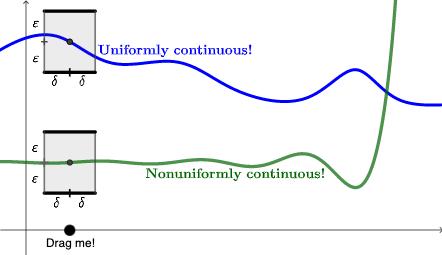
This example illustrates the difference between uniform and non-uniform continuity. Key mathematical concepts include continuity. GeoGebra commands such as OrthogonalLine, Spline, Intersect are used to construct the function graph and related geometric objects. Suitable for high school mathematics education and learning.
GeoGebra Commands & Parameters
OrthogonalLine(PD, xAxis) → gSpline(L1, 3) → aIntersect(g, a) → J, J_{1}If(J ≟ J, J, J_{1}) → J1Intersect(f, g, (0.6903277834804339, 1.9925685358884224)) → KOrthogonalLine(J1, g) → hIntersect(h, yAxis) → RRGOrthogonalLine(PD', xAxis) → iOrthogonalLine(PD'', xAxis) → jOrthogonalLine(RRF'', yAxis) → kOrthogonalLine(RRF', yAxis) → lIntersect(j, l) → LIntersect(i, l) → MIntersect(i, k) → NIntersect(j, k) → OPolygon(O, N, M, L) → q1, o, n, m, l_1Midpoint(O, N) → RMidpoint(O, L) → SMidpoint(S, L) → TMidpoint(O, S) → UMidpoint(O, R) → VMidpoint(R, N) → WOrthogonalLine(RRG, yAxis) → qOrthogonalLine(RRG'', yAxis) → rOrthogonalLine(RRG', yAxis) → sIntersect(r, j) → PIntersect(i, r) → QIntersect(s, i) → ZIntersect(j, s) → A_1Polygon(P, Q, Z, A_1) → q2, p_1, q_1, z_1, a_1Midpoint(A_1, P) → B_1Midpoint(P, B_1) → E_1Midpoint(A_1, B_1) → F_1Midpoint(A_1, Z) → G_1Midpoint(Z, G_1) → H_1Midpoint(A_1, G_1) → I_1
AI Drawing Prompt Reference
Draw a coordinate-plane diagram comparing uniform and non-uniform continuity by constructing several curves and a sequence of related geometric points. Start from a base function and a set of key parameter points; through these points draw vertical lines and use them to generate intersections with an auxiliary smooth spline curve built from the given points. Compute additional intersections involving the spline and the vertical lines, and also form points where selected lines meet the y-axis. Connect appropriate intersection points to form two neighboring quadrilaterals, then take midpoints on their edges to create interior division points, producing a structured geometric layout illustrating the continuity comparison.
The prompt above was compiled from the original drawing commands and is for reference only.