
Stereographic Projection: Mapping the Sphere to the Plane
Loading the math board and drawing, please wait…
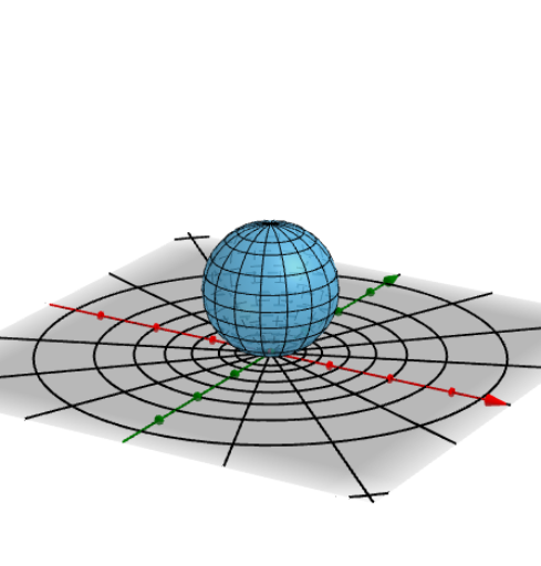
This GeoGebra example demonstrates the stereographic projection, a classical geometric transformation that maps points on a sphere (except the north pole) to the equatorial plane via rays emanating from the north pole. It visually illustrates the correspondence between spherical and planar points, highlighting the conformal (angle-preserving) nature of the projection. Core mathematical concepts include spherical geometry, projection transformations, conformal mapping, and the connection to the unit circle and complex plane. The construction uses GeoGebra commands such as Point, Sphere, Line, Rotate, Intersect, PointIn, Circle, Plane, OrthogonalLine, Mirror, Locus, and Midpoint to build the sphere, projection rays, intersection points, auxiliary circles, perpendiculars, mirrored points, and loci. Dynamic objects (a, f, g, α, etc.) allow interactive exploration of how points move between the sphere and the plane. Suitable for high school to university-level geometry courses, particularly for teaching solid geometry, analytic geometry, and introductory complex analysis, helping students grasp the topological and metric relationships between the sphere and the plane.
GeoGebra Commands & Parameters
Point(zAxis) → ASphere(A, 1) → aLine(A, yAxis) → fLine(A, xAxis) → gRotate(a, α, f) → a'Rotate(a', β, g) → a''Rotate(a'', γ, zAxis) → a'''Intersect(f, a''') → B, CPointIn(a''') → D1PointIn(a''') → D2PointIn(a''') → D3PointIn(a''') → D4PointIn(a''') → D5PointIn(a''') → D6Line(D1, D2) → hCircle(A, 1, h) → d3Plane(A, D1, D4) → bOrthogonalLine(A, b) → iCircle(A, 1 / 4, i) → e1Intersect(h, e1) → D, C1OrthogonalLine(C1, b) → jCircle(C1, 1 / 4, j) → e2Intersect(h, e2) → F, C2OrthogonalLine(C2, b) → kCircle(C2, 1 / 4, k) → e3Intersect(h, e3) → H, C3Mirror(C1, A) → C1'Mirror(C2, A) → C2'Mirror(C3, A) → C3'Intersect(k, a''') → E, GIntersect(j, a''') → I, JOrthogonalLine(C3, b) → lIntersect(l, a''') → K, LCircle(C3, Distance[C3, K], h) → d4Circle(C2, Distance[C2, E], h) → d6Circle(C1, Distance[C1, I], h) → d8Mirror(d4, A) → d5Mirror(d6, A) → d7Mirror(d8, A) → d9Rotate(D3, (-((45 * ° / 2))), h) → E1Rotate(D3, (-(45°)), h) → E2Rotate(D3, (-(45° + (45 * ° / 2))), h) → E3Line(D3, A) → mCircle(D3, D1, D2) → c9Circle(D1, E1, D2) → c2Circle(D1, E2, D2) → c3Circle(D1, E3, D2) → c4Circle(D5, D1, D2) → c5Rotate(D5, (-((45 * ° / 2))), h) → E4Rotate(E4, (-(45°)), h) → E5Rotate(D5, (-(45°)), h) → E6Circle(E4, D1, D2) → c6Circle(E6, D1, D2) → c7Circle(E5, D1, D2) → c8Point(d4) → M1Point(d6) → M2Point(d8) → M3Point(d3) → M4Point(d9) → M5Point(d7) → M6Point(d5) → M7Line(Z, M1) → nIntersect(n, xOyPlane) → TLocus(T, M1) → loc1Line(Z, M2) → i_1Intersect(i_1, xOyPlane) → ULocus(U, M2) → loc2Line(Z, M3) → j_1Intersect(j_1, xOyPlane) → VLocus(V, M3) → loc3Line(Z, M4) → l_1Intersect(l_1, xOyPlane) → WLocus(W, M4) → loc4Line(Z, M5) → m_1Intersect(m_1, xOyPlane) → A_1Locus(A_1, M5) → loc5Line(Z, M6) → n_1Intersect(n_1, xOyPlane) → B_1Locus(B_1, M6) → loc6Line(M7, Z) → p_1Intersect(p_1, xOyPlane) → C_1Locus(C_1, M7) → loc7Point(c2) → F1Point(c3) → F2Point(c4) → F3Point(c5) → F4Point(c6) → F5Point(c9) → F6Point(c7) → F7Point(c8) → F8Line(F6, Z) → a4Line(F1, Z) → a5Line(Z, F2) → a6Line(Z, F3) → a7Line(Z, F4) → a1Line(Z, F5) → b_1Line(Z, F7) → a2Line(Z, F8) → a3Intersect(a4, xOyPlane) → L_1Intersect(a5, xOyPlane) → M_1Intersect(a6, xOyPlane) → N_1Intersect(a7, xOyPlane) → O_1Intersect(a1, xOyPlane) → P_1Intersect(b_1, xOyPlane) → Q_1Intersect(a2, xOyPlane) → R_1Intersect(a3, xOyPlane) → S_1Locus(L_1, F6) → loc8Locus(M_1, F1) → loc9Locus(N_1, F2) → loc10Locus(O_1, F3) → loc11Locus(P_1, F4) → loc12Locus(Q_1, F5) → loc13Locus(R_1, F7) → loc14Locus(S_1, F8) → loc15Midpoint(C3, D1) → MOrthogonalLine(M, b) → tIntersect(t, a''') → N, OCircle(M, Distance[M, N], h) → d1Mirror(d1, A) → d2Point(d1) → M8Point(d2) → M9Line(M8, Z) → f_1Line(Z, M9) → g_1Intersect(f_1, xOyPlane) → PIntersect(g_1, xOyPlane) → QLocus(P, M8) → loc16Locus(Q, M9) → loc17
AI Drawing Prompt Reference
Create a stereographic projection, mapping points on a unit sphere to a plane via rays. Start by drawing a unit sphere, then draw two intersecting rays with the sphere. Rotate the sphere around these rays to generate intersection points and auxiliary circles. Finally, use mirroring and rotation to create additional points and circles, illustrating the properties of the projection.
The prompt above was compiled from the original drawing commands and is for reference only.