
Sine Function via Regular Polygon Construction
Loading the math board and drawing, please wait…
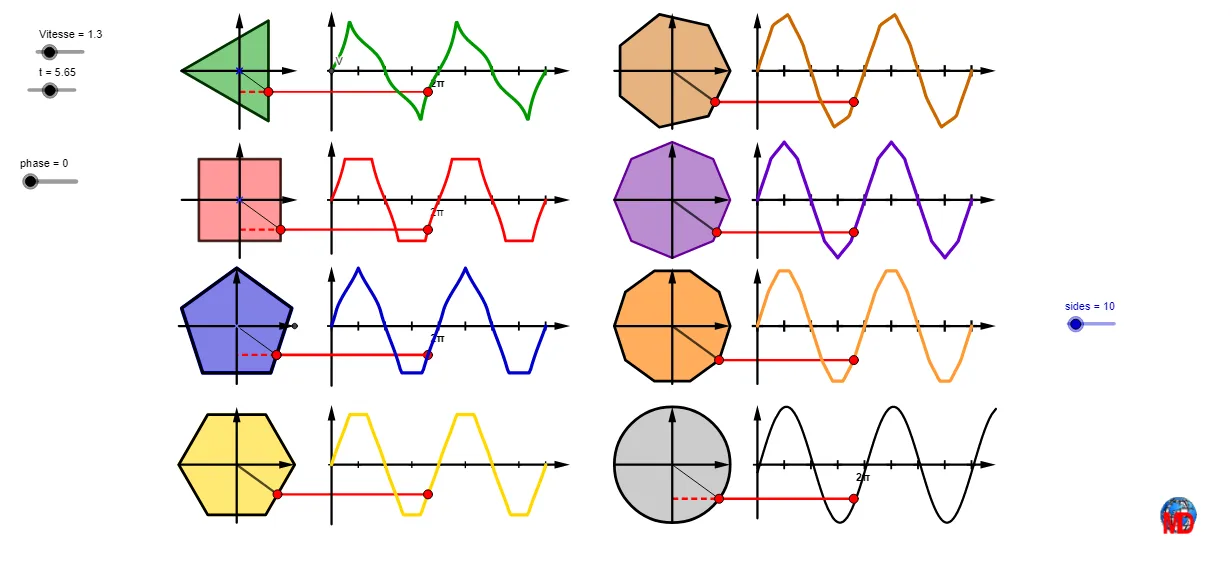
This example demonstrates how the sine function behavior can be visualized through the geometric construction of regular polygons, highlighting periodic patterns as the phase and/or the number of sides changes. It centers on key concepts from trigonometry and geometry: the relationship between central angles and trigonometric values (sin), parameterization by angle phase, and the use of geometric measures such as lengths or perimeters that correspond to function-related quantities. The construction uses GeoGebra commands including Sequence and If to generate parameter sequences and conditional cases (e.g., phase and sides), Rotate together with Ray/Line/Segment to build polygon edges and rotated configurations, and Polygon with Circle, Intersect, and Point to form the regular polygon and its notable intersection points. Distances and Vectors extract measurable geometric information, while Locus captures how the evolving configuration traces a curve linked to the sine behavior. Mod and transformation commands like Translate (and Mirror where applicable) implement periodicity, alignment, and symmetry. The result is suited for secondary school through early university students, especially for teaching/learning trigonometry through geometry-based visualization and interactive function understanding.
GeoGebra Commands & Parameters
Mod(sides, 4) → aaSequence(K + ((R * cos(i + π / 3 + (phase * π / 6))), (R * sin(i + π / 3 + (phase * π / 6)))), i, 0, 6.28319, 2.0944) → liste2Mod(sides, 2) → nnIf(aa ≟ 1, Rotate[B, π / 5, A], Rotate[B, ((-π)) / 5, A]) → BBIf(aa ≟ 0, BB, F) → FFRotate(B, t, A) → B'Ray(A, B') → kSegment(B, E) → hSegment(A, B') → bSequence(Rotate[FF, i + (phase * π / 10), A], i, 0, 6.28319, (2 * π / 5)) → liste1Polygon(liste1) → pIntersect(k, p) → K_2Intersect(b, p) → DPoint(p, m) → M_1Perimeter(p) → perLine(M_1, xAxis) → aIntersect(a, yAxis) → CCircle(A, R) → cDistance(A, C) → disDistance(B, J) → ddSegment(D, P) → dSegment(F, G) → gVector(G, F) → uVector(I, B) → vSegment(H, A) → iSegment(D, H) → jLocus(P, t) → lieu1Rotate(L, t, K) → L'Rotate(M, 120°, K) → M'Rotate(M, 240°, K) → M'_1Ray(M, M') → a_1Ray(M, M'_1) → l_1Polygon(liste2) → poly2Ray(K, L') → lIntersect(l, poly2) → NSegment(K, N) → d_1Distance(L, JJ) → dtSegment(N, PT) → nLocus(PT, t) → lieu2Sequence(O + ((R * cos(i + π / 4 + (phase * π / 8))), (R * sin(i + π / 4 + (phase * π / 8)))), i, 0, 6.28319, 1.5708) → liste3Rotate(Q, t, O) → Q'Ray(O, Q') → rPolygon(liste3) → poly1Intersect(r, poly1) → SSegment(O, S) → e_1Distance(Q, T) → dcLocus(PC, t) → lieu3Segment(S, PC) → f_1Vector(V, W) → wCircle(Z, R) → g_1Rotate(A_1, t, Z) → B_1Segment(Z, B_1) → h_1Segment(B_1, D_1) → i_1Vector(C_1, G_1) → zVector(E_1, F_1) → u_1Vector(O_1, H_1) → v_1Segment(K_2, A) → j_1Mirror(Q, O) → Q'_1Mirror(L, K) → L'_1Mirror(A_1, Z) → I_1Vector(L'_1, L) → w_1Vector(I_1, A_1) → z_1Vector(Q'_1, Q) → k_1Mirror(A, M) → A'Mirror(K_1, O) → L_{1}Mirror(J_1, Z) → N_{1}Vector(N_{1}, J_1) → m_1Vector(L_{1}, K_1) → n_1Mirror(A, M) → A'_1Mirror(K, M) → K'Mirror(M, K) → M'_2Vector(M'_2, M) → q_1Segment(Q_1, S) → r_1Segment(P_1, N) → s_1Segment(R_1, B_1) → t_1Sequence(V + (i, 0), i, 0, 14, 1.5708) → liste4Sequence(O_1 + (i, 0), i, 0, 14, 1.5708) → liste5Sequence(E_1 + (i, 0), i, 0, 14, 1.5708) → liste6Sequence(C_1 + (i, 0), i, 0, 14, 1.5708) → liste7Sequence(Text[i / 2.5 + "π", Element[liste7, i] - (0.51, 0.95)], i, 0, Length[liste5], 5) → liste9Sequence(Text[i / 2.5 + "π", Element[liste6, i] - (0.51, 0.95)], i, 0, Length[liste5], 5) → liste10Sequence(Text[i / 2.5 + "π", Element[liste4, i] - (0.51, 0.95)], i, 0, Length[liste5], 5) → liste11Polygon(V_{1}, Z_{1}, A_2, W_{1}) → q1, f_2, g_2, a_2, h_2Polygon(W_{1}, B_2, C_2, A_2) → q2, i_2, b_2, c_2, j_2Polygon(B_2, D_2, E_2, C_2) → q3, k_2, d_2, e_2, l_2Polygon(D_2, F_2, G_2, E_2) → q4, m_2, n_2, p_2, q_2Translate(q_1, Vector[K, V]) → u_2Vector(V - (0, 3.5), V + (0, 3.5)) → v_2Vector(O_1 - (0, 3.15), O_1 + (0, 3.45)) → w_2Vector(E_1 - (0, 3.5), E_1 + (0, 3.5)) → r_2Vector(C_1 - (0, 3.15), C_1 + (0, 3.5)) → s_2Sequence(Text[i / 2.5 + "π", Element[liste5, i] - (0.51, 0.95)], i, 0, Length[liste5], 5) → liste8Vector(H_2 - (R, 0), H_2 + (R, 0)) → t_2Vector(H_2 - (0, R), H_2 + (0, R)) → u_3Sequence(Rotate[H_2 + (R, 0), i + (phase * π / 12), H_2], i, 0, 6.28319, (2 * π / 6)) → l1Polygon(l1) → poly3Vector(I_2 - (0, 3.5), I_2 + (0, 3.5)) → v_3Vector(I_2, (14, y(H_2))) → w_3Sequence(I_2 + (i, 0), i, 0, 14, 1.5708) → liste6bRotate(H_2 + (R, 0), t, H_2) → J_2Ray(H_2, J_2) → f_3Intersect(f_3, poly3) → L_2Segment(H_2, L_2) → g_3Locus(M_2, t) → lieu4Segment(L_2, M_2) → h_3Vector(L_1 - (0, R), L_1 + (0, R)) → a_3Vector(N_2 - (0, R), N_2 + (0, R)) → b_3Vector(O_2 - (0, R), O_2 + (0, R)) → c_3Vector(L_1 - (R, 0), L_1 + (R, 0)) → d_3Vector(N_2 - (R, 0), N_2 + (R, 0)) → e_3Vector(O_2 - (R, 0), O_2 + (R, 0)) → i_3Vector(P_2 - (0, R), P_2 + (0, R)) → j_3Vector(Q_2 - (0, R), Q_2 + (0, R)) → k_3Vector(R_2 - (0, R), R_2 + (0, R)) → l_3Vector(P_2, (39, y(P_2))) → m_3Vector(Q_2, (39, y(Q_2))) → n_3Vector(R_2, (39, y(R_2))) → p_3Sequence(Rotate[L_1 + (R, 0), i + (phase * π / 14), L_1], i, 0, 6.28319, (2 * π / 7)) → l2Sequence(Rotate[N_2 + (R, 0), i + (phase * π / 16), N_2], i, 0, 6.28319, (2 * π / 8)) → l3Sequence(Rotate[O_2 + (R, 0), i + (phase * π / ((2 * sides))), O_2], i, 0, 6.28319, (2 * π / sides)) → l4Polygon(l2) → poly4Sequence(P_2 + (i, 0), i, 0, 14, 1.5708) → liste6cSequence(Q_2 + (i, 0), i, 0, 14, 1.5708) → liste6dSequence(R_2 + (i, 0), i, 0, 14, 1.5708) → liste6ePolygon(l3) → poly5Polygon(l4) → poly6Rotate(L_1 + (R, 0), t, L_1) → S_2Rotate(N_2 + (R, 0), t, N_2) → T_2Rotate(O_2 + (R, 0), t, O_2) → U_2Ray(L_1, S_2) → q_3Ray(N_2, T_2) → r_3Ray(O_2, U_2) → s_3Intersect(q_3, poly4) → V_2Intersect(r_3, poly5) → W_2Intersect(s_3, poly6) → Z_2Segment(L_1, V_2) → t_3Segment(N_2, W_2) → f_4Segment(O_2, Z_2) → g_4Segment(V_2, A_3) → h_4Segment(W_2, B_3) → i_4Segment(Z_2, C_3) → j_4Locus(A_3, t) → lieu5Locus(B_3, t) → lieu6Locus(C_3, t) → lieu7Polygon(liste3) → poly7Polygon(liste2) → q5Polygon(liste1) → poly8Polygon(l1) → poly9Polygon(l2) → poly10Polygon(l4) → poly11
AI Drawing Prompt Reference
In the same coordinate plane, construct a regular polygon whose vertices are generated by rotating around a fixed center while a phase parameter changes continuously. Build auxiliary rays/lines from reference points, intersect them with the moving polygon to obtain key intersection points, and measure relevant distances between the center and the intersection locations. For the chosen moving point(s) related to these intersections, trace a locus as the parameter varies to reveal a sine-like periodic curve. Then repeat the construction with a different set of initial angle offsets and step size, producing a second regular polygon with its own intersection point(s) and a second locus, while keeping the center and supporting rays/segments that define the relationships.
The prompt above was compiled from the original drawing commands and is for reference only.